Thanks for the offer Hans. Now you've put me on the spot 🙂 I'm open to suggestions but I think the frequency would have to be low enough that the envelope was not too small a fraction of it or there wouldn't be sufficient "stretching"? If we use the ratio of 4:1 as used earlier, how short an envelope could be used to discern frequency? I don't think this is going to work is it? 😱
I’ll try to come with a “stretcher” tomorrow
Hans
You are right. My favourite plots showing this is a sum of sine waves with same spectra - the only difference is a phase of sine waves. This results in totally different time waves. Same amplitude spectra, different time plots - because phase info is missing.
IIRC Nico Ras showed something similar a few years ago. I was quite surprised at how different the waveform looked without the phase info.
Thanks, I think I'll need it by then....I’ll try to come with a “stretcher” tomorrow
Hans

Let's keep backhanded comments out of this thread. The purpose of this is a testing ground after the ego failure of the BT thread. Let's not lose the opportunity to have a sandbox. This one can determine who is going to be a part of the forum and who is not.
Thank your for not only your understanding, but cooperation.
Yes. 5 uSec is pretty much the ITD number bandied about. I do not necessarily agree that system bandwidth need be 200 kHz however (1/5usec), nor 450 kHz from nordmark at 1.5 uSec. The only worry is inter channel stability at the 5usec level, from mike to speaker.We have been talking about Fs near CD sampling frequency. While humans seem to have a nominal frequency upper limit of about 20k, but Kuchnur’s (sp?) research shows that the temporal response goes higher in frequency than that Fs.
Information for prospective students
dave
Edit: as to listening to test tone for freq shift, make it easier by scaling the brickwall. Use a 10k Fs, try both modulation techniques using 8/3, run the signal half a second.
Compare pre and post filter with 8k modulated raised sine 3k, and sin(8)cos(3).
Jn
Last edited:
So the SofS thru the denser SF6 will be slower.
135 meters per second.
Jn
When I was doing my own live recordings to get Masters for equipment listening evaluations.... i was a lot younger than i am now. That is when i first heard the differences between CD made off a good analog 30 ips 1/2 track master.
But today? I would think many of us over 50 here cannot hear much above 8-10KHz now.
Just aging ears.
I would therefore place zero cred in results from anyone with less than perfect hearing.


THx-RNMarsh
But today? I would think many of us over 50 here cannot hear much above 8-10KHz now.
Just aging ears.
I would therefore place zero cred in results from anyone with less than perfect hearing.
THx-RNMarsh
Last edited:
Ha! There was also that old reel rocking trick by slowing playback down, which led me to this experiment.Then it seems to me an audibility test of the idea could be devised by shifting everything down in frequency?
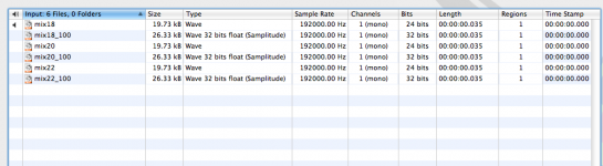
These are Hans' latest 192k test files downshifted four times to 48k. Test signals are now in 4.5k - 5.5k range. See if any of you can hear anything unusual besides missing upper sideband, lack of which now obviosly contributes to sound "signature".
The audio data itself is untouched and there is no downsampling. All I did was some file format conversion (wav to sd2 and back to wav on a Mac) for the purpose of changing file header.
P.S. Hans, your unprocessed 192k files are in 24 bit fixed format, but filtered are in 32 bit float. Just FYI, in case someone has problems in playing them back.
Attachments
Last edited:
Jn,I've no idea how to interpret the different filters w/r to the time symmetry, others here are far more advanced in that aspect.
1. Don't you think that the test results should not be ignored?
2. I won't let you off the hook that easily 😉
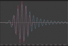
Back in the old thread you said (simplified) that 20k IN thru LP filter leads to 18k OUT and all that you needed is to look at zero crossings.
I deliberately introduced one variable in the test - a different type of LP filter and there you go - you have your zero crossings. And what is the OUT frequency in these two cases??
Even without using a ruler to determine T, I can see that the zero crossings and therefore the so called "f OUT" is different for both of the filters I used.
IMO, if the "f OUT" is dependent on LP filter type, something is wrong here.
Any thoughts?
P.S. I didn't post any FFTs of my experiments, because they showed what they were supposed to show.
P.P.S. For those who didn't read my previous posts - fs was at 88.2k.
Attachments

Last edited:
Yes, thanks for the suggestion. When I spoke of transposing everything downwards I meant the brickwall too. I'd suggest as short an envelope as possible too, may be less than half a second? Ideally shouldn't the raised sine be the envelope?Edit: as to listening to test tone for freq shift, make it easier by scaling the brickwall. Use a 10k Fs, try both modulation techniques using 8/3, run the signal half a second.
Compare pre and post filter with 8k modulated raised sine 3k, and sin(8)cos(3).
Thank you very much, I think that's very useful? I was wondering whether an envelope around about a tenth of a second would be sufficient, it seems so. I can't hear any frequency shifting.Ha! There was also that old reel rocking trick by slowing playback down, which led me to this experiment.
These are Hans' latest 192k test files downshifted four times to 48k. Test signals are now in 4.5k - 5.5k range. See if any of you can hear anything unusual besides missing upper sideband, lack of which now obviosly contributes to sound "signature".
The audio data itself is untouched and there is no downsampling. All I did was some file format conversion (wav to sd2 and back to wav on a Mac) for the purpose of changing file header.
P.S. Hans, your unprocessed 192k files are in 24 bit fixed format, but filtered are in 32 bit float. Just FYI, in case someone has problems in playing them back.
Matt,
So the SofS thru the denser SF6 will be slower.
From Wikipedia:Thiele/Small parameters - Wikipedia
So Vas is proprotional to the square of the speed of sound.
dave
Hi Dave,
Now I see where you (and perhaps W&D) went wrong. Vas is NOT proportional to the speed of sound. You have been wrongfooted by the formula.
Vas - Equivalent Compliance Volume, i.e. the volume of air which, when acted upon by a piston of area Sd, has the same compliance as the driver's suspension:
Indeed, one formula for Vas is as you mention:
-quote-
Vas = ρ x c2 x Sd2 x Cms (c2 = c squared)
where ρ is the density of air (1.184 kg/m3 at 25 °C), and c is the speed of sound (346.1 m/s at 25 °C).
-unquote-.
However: the speed of sound in a gas C=sqrt(Ks/ρ). So look back at the formula for Vas. In the ρ x c2 term, ρ disappears after calculation and only Ks remains.
Ks is the modulus of bulk elasticity for gasses. This is the actual measure of the gas spring behind the cone and is required for the calculation. It is the same for all gasses at the same temperature.
In short, it is exactly as I said. For aligment, density of the gas filling the enclosure is irrelevant.
As a further note: when it comes to standing waves, a heavier gas will only make matters worse. The reason is that a given enclosure will support standing waves up to a lower frequency when filled with a heavier gas. Plus, there will be more energy in them.
Vac
Last edited:
You are over my head. And too late, too tired to be bothered checking after you. All i know is it worked.
Vas goes down, then box size goes down.
dave
Vas goes down, then box size goes down.
dave
Planet 10, I know the new rules, but I am disappointed. If you can't respond with a substantial response, then please don't. Repeating a fallacy doesn't make it right. I feel compelled to post this, because it is a clear matter which I want people to understand clearly.
Once, around 45 years ago a SF6 filled electrostatic was very popular with the hi end of audio. Mark Levinson had a pair, for example in 1973 or so. The problem with the very first edition was that there was no high frequency output, but they did not admit it at first. We found out after I modified the Phase Linear 700 bias to remove the xover distortion. Then the 'relatively balanced' sound of the speakers went to 'dead sounding' and Mark was forced to add a tweeter (electrostatic in his case).
Later, when the hi frequency rolloff was made obvious, the electrostatic manufacturer added the only 'practical' super tweeter at the time, which was an piezo horn from Motorola. We all tried them and they MEASURED pretty good, but they always seemed to sound slightly
lousy in practice. DW went for the piezo. They went out of business after some years.
As a further note: when it comes to standing waves, a heavier gas will only make matters worse. The reason is that a given enclosure will support standing waves up to a lower frequency when filled with a heavier gas. Plus, there will be more energy in them.
How big the enclosure ? In *normal* speaker enclosures there are no standing waves; it's an argument that resurrects every day and I'm getting tired of remarking that. In an enclosure like a room where the distances and stimulus are appropriate, the SW might take place > the same room is defined by the modes and reverb.
Moreover, inside an enclosure there are no *waves* but chaotic movement of particles.
Since I see you are versed in the loudspeaker & associated branch I expect some insightful answer.
Tony
Tony,
In a properly designed enclosure, there are no standing waves because of the application of damping material.
Without that damping material, standing waves will occur at dimensions of half the wavelength in pretty much any direction you can find inside the enclosure. Not only between the walls, but also diagonally. These standing waves show up in measurements as typical up-down resonance wiggles. It is the same as room modes, the same calculus applies.
As a matter of fact, when you do loudspeaker design right, you have a thorough look at those wiggles in a measurement and try to correlate them to internal dimensions of the enclosure. If they are correlated, you know there are standing waves and that you need to apply more damping material to get rid of them.
Not a bad link I found on first try:
Internal standing waves - How to eliminate them from loudspeaker boxes
Best is to keep each driver in an enclosure of which the dimensions are smaller than half the wavelength of the highest frequency that driver has to play. This is only practical for bass drivers and that is also the reason why subwoofers don't need internal damping material as a rule.
Best is to keep each driver in an enclosure of which the dimensions are smaller than half the wavelength of the highest frequency that driver has to play. This is only practical for bass drivers and that is also the reason why subwoofers don't need internal damping material as a rule.
As a side note Jordan says this about the VTL enclosure, which is only 70mm deep internally
"Will the shallow VTL and DCR enclosures cause audible reflections behind the Eikona?
On the contrary, it will raise their frequency and make them easier to absorb through use of acoustic damping material placed behind the Eikona."
FAQ - E J Jordan Designs
- Home
- Member Areas
- The Lounge
- The Black Hole......