I don't think thermal conductivity in a solid is affected by gravity. I think heat should spread equally in all directions with in the base plate. Depending how wide a sink you have, it may, of course, not get as hot at the ends as it is in the center. There is however, an argument to be made in favor of mounting lower on the sink as that's where the updraft will be cooler, so the hot spot will see a greater gradient, and therefor higher rate of transfer.
Since we're talking about sink size, I noticed a pattern (beyond just the MoFo) of about one cubic inch of heat sink volume per watt dissipated. The MoFo doc lists 32W dissipation at 19V, which lead me to purchase a pair of these: Alpine 12 Passive | Silent CPU Cooler for Intel CPU | ARCTIC. ~48 cubic inches, rated for TDP of 47W.
Are they too small for a little MoFo?
It looks small.
The fine print: "* Tested in Tower CPU Case with 2 x 120 mm Fans in PWM standard mode".
So it is relying on forced air movement.
It also says 78 degrees C - if that is heatsink temperature, it's way too high.
Alpine 12 Passive | Silent CPU Cooler for Intel CPU | ARCTIC
shows size as 95mm x 95mm x 69mm, and weighing 508 grams.
It doesn't look like it will work.
Wow - I sure missed that. Marketing a cooler as passive and touting ratings w/ a fan - wow.
It also says, "CPUs with a TDP > 35 W may reduce the clock during longer periods of full load in PCs with absolutely no fan."
If ambient is 22C, 78C is 56C above that. 56C/35W = 1.6C/W. Doc says MoFo wants 0.78C/W.
Well, at least they were cheap...
It also says, "CPUs with a TDP > 35 W may reduce the clock during longer periods of full load in PCs with absolutely no fan."
If ambient is 22C, 78C is 56C above that. 56C/35W = 1.6C/W. Doc says MoFo wants 0.78C/W.
Well, at least they were cheap...
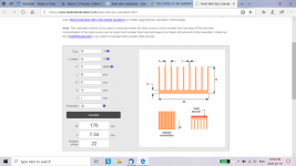
Here is something I found:
Heat Sink Size Calculator
The calculator is non-conservative in that it assumes the device being cooled covers the heat sink 100 percent, which is not the case with the mosfet.
I entered the information that I could find and estimated others, and it estimates a size of 95mm x 176mm, and also requires fin clear spacing of 7.34mm to facilitate air flow. The cpu cooler doesn't meet these dimensional requirements.
As you said, it was cheap.🙂
Attachments
Pretty sure my heatsinks are these: 10.080" Wide Extruded Aluminum Heatsink - HeatsinkUSA
10" wide with 2.5" fins
Kind regards,
Drew
10" wide with 2.5" fins
Kind regards,
Drew
Does anyone have, or know where to get boards for a cap multiplier? Seems like something that the DIY store should sell.
Any drawbacks from using a cap Mx on a MOFO compared to other options?
I like the protection from DC interruption, but probably just adding some caps, or a CRC would be the other options.
What is recommended?
Thanks Mark
Any drawbacks from using a cap Mx on a MOFO compared to other options?
I like the protection from DC interruption, but probably just adding some caps, or a CRC would be the other options.
What is recommended?
Thanks Mark
Last edited:
Check out the SLB Class A psu. It’s a full featured (active rectifier, CRC and CapMx) one board power supply. Use the single rail version for MOFO.
The SLB (Smooth Like Butter) Active Rect/CRC/Cap Mx Class A Power Supply GB
The SLB (Smooth Like Butter) Active Rect/CRC/Cap Mx Class A Power Supply GB
Check out the SLB Class A psu. It’s a full featured (active rectifier, CRC and CapMx) one board power supply. Use the single rail version for MOFO.
The SLB (Smooth Like Butter) Active Rect/CRC/Cap Mx Class A Power Supply GB
This looks like a pretty slick solution, just ordered a pair of single rail SLB boards.
Thanks
Mark
Dear Gentlemen,
wanting to build myself a linear and regular power supply for my successful Mofo,
I would like to let have my both 19V / 4,74 A power supply Mean Well GST90A19-P1M.
I can make a good price, if anybody is interested...
Thank you
Yours sincerely
TYM
wanting to build myself a linear and regular power supply for my successful Mofo,
I would like to let have my both 19V / 4,74 A power supply Mean Well GST90A19-P1M.
I can make a good price, if anybody is interested...
Thank you
Yours sincerely
TYM
1) Anyone ever measured MOT secondary voltage in MoFo circuit?
https://www.tubecad.com/2015/06/13/..., Choke-Load, Capacitor-Coupled Amplifier.png what I really mean, might be unpractical, yet still, could one make a hybrid pattern?
https://www.tubecad.com/2015/06/13/..., Choke-Load, Capacitor-Coupled Amplifier.png what I really mean, might be unpractical, yet still, could one make a hybrid pattern?
Michael, there are measurements with other output chokes ?
Here were some measurements that I made using a MOFO with a microwave oven transformer (MOT) with measured inductance of circa 67mH, 0.5ohm DCR.
Build This MoFo!
4Vpp into 8ohms:
O-scope 26.8Vpp into 8ohms for 11wrms:
9.6Vpp 1kHz square wave:
The MOTs look like this and are typically $25 to $40 on eBay (keyword search "MD-803AMR"):
And here is what my build using MOTs looks like:
Michael, there are measurements with other output chokes ?
I tried a few different chokes, including air cores, but I'm away from home and can't get to any of my notes. Best results, as I recall were with the 50mH and up. 🙂
- Home
- Amplifiers
- Pass Labs
- Build This MoFo!