I remember the Musique Industrie amps but they are very old, around mid 70's.
Same era as made-in-Holland Novanex, both long defunct brands.
You *could* use 2N3055 with up to +/-50V rails, sort of, because way back then competition was based on quality, so good brands (RCA, Motorola) regularly surpassd specs, so buyng extra ones and selecting you could find quite a few extra strong ones.
Today competition is based on price only, so good brands *just* meet published specs.
So forget modern 2N3055, get at least MJ15015 or even better NPN MJ1502x , currently the "universal transistor" in TO3 metallic case.
From your description, a very popular architecture way back then was to use 4 x 2N3055 driven by 2 more, so drivers had an easy load to drive.
Here I am showing a similar amp, maybe Musique Industrie copied ... ahem .... was "inspired" by it or a close relative
Here one 40411 (the 2N055 muscular cousin) drives three others on each rail, which allows using weak 40409/40410 drivers (weaker than MJE340/350 or BD139/140, go figure).

It won´t be too different from this one, although Acoustic 361 uses single rail supply so it needs a speaker out capacitor.
I suggest you post a couple power amp board pictures, we might recognize something.
Same era as made-in-Holland Novanex, both long defunct brands.
You *could* use 2N3055 with up to +/-50V rails, sort of, because way back then competition was based on quality, so good brands (RCA, Motorola) regularly surpassd specs, so buyng extra ones and selecting you could find quite a few extra strong ones.
Today competition is based on price only, so good brands *just* meet published specs.
So forget modern 2N3055, get at least MJ15015 or even better NPN MJ1502x , currently the "universal transistor" in TO3 metallic case.
From your description, a very popular architecture way back then was to use 4 x 2N3055 driven by 2 more, so drivers had an easy load to drive.
Here I am showing a similar amp, maybe Musique Industrie copied ... ahem .... was "inspired" by it or a close relative
Here one 40411 (the 2N055 muscular cousin) drives three others on each rail, which allows using weak 40409/40410 drivers (weaker than MJE340/350 or BD139/140, go figure).
It won´t be too different from this one, although Acoustic 361 uses single rail supply so it needs a speaker out capacitor.
I suggest you post a couple power amp board pictures, we might recognize something.
Last edited:
One of the reasons for that circuit using such a “big” driver (40411) is because it is a fully class B current dumper. Note the 0.47 ohm base-emitter resistor on the outputs, and only two diodes in the bias stack. The output stages stays cut off and you operate completely off the drivers up until you put out about an amp and a half of load current. Above that, three outputs kick in. All the idle bias current is in the driver. Amps biased like this have no issues with thermal runaway, which is probably why they did this. In its day, RCA40411 was THE workhorse medium voltage hometaxial, way better than any 2N3055. Its generic # was the 2N6254. I still have a couple dozen 6254’s pulled from working decommissioned power supplies. A few dozen more have found their way into vintage amps and lab power supplies over the years. They haven’t completely disappeared yet - I’ve seen them at Skycraft from time to time.
Secrets of the 1970's revealed. My ST120 from 1970 was built of RCA 40409/40410 drivers, and 40411 outputs. Datasheets have never been available to me. Dropped from the RCA 1972 databook. Now the 2n6254 datasheet from Central is stripped down with nothing but Vcesus, power and switching parameters listed.In its day, RCA40411 was THE workhorse medium voltage hometaxial, way better than any 2N3055. Its generic # was the 2N6254.
One set drivers survived 50 years, sounded better on hi-freq instruments than NTE49/50 and TIP41c/42c. Superior Ft probably, MJE15028/29 seem to equal hi freq sound quality although they won't fit the old PCB. Test LP's the TIP's butchered, When I Fall in Love Peter Nero, (top octave solo piano) Martin Denny Hawaii (tinkly percussion).
Last edited:
I saw the old 404xx data sheets in an old RCA book which unfortunately was not mine. It was the only one I ever saw them in apart from just random app notes. It listed the 3773, 3437, and 6259 on the same page - back when all were homo’s. I had the 1982 book, which actually had the 15024 in it! Still had the 1B05, too. AND had the 3773, 6609, MJ15003, and 15004 listed on the same data sheet, using the same set of typical characteristic graphs but different specs limits for each. I had long suspected that Motorola was making the same damn parts for the 2N and MJ numbers. Even RCA was. The “RCA” or “TA” numbers were usually just selected versions of generics (2N) and the data sheets always pointed you to the generic number if there was one, so that you could go look up supplemental data. Motorola wasn’t so forthcoming. The only place you could find cross references for the SJ types was in Peavey’s service documentation. Can’t find the book right now, but I DID find the 1989 Japanese transistor manual when I was looking for it so that’s a win.
Here are the pictures!
i do have a scope and a generator but my scope is out of order - waiting for a new optocoupler !
All transistors have been unsoldered and checked on my cheap but effective chineese transistor tester...
the circuit uses only 2 diodes : one tiny black one with funny marking (SSC PLZ? can't find anthing related) and a BC109 used as a zener...
Attachments
Last edited:
I think the 40411 was a selected 2N3772, not a 2N6254.
The only place I have seen any SOA chart for the 40411 is in the RCA 1971 Designer's Handbook. It shows 20A max. current and 60V for S/B power derating, 80V max. The spec. sheet says 800kHz typical. The 2N3772 also shows 800kHz typical but 200kHz minimum. On the other hand the 2N6254 states 800kHz minimum.
The 40411 might have been good for dumping power but not hifi. The 2N6254 would have been a better 2N3055, for sure.
Of course all this is moot as newer devices outperform all those old 'homos'.
I find the gain test at 2 v or 9 v of a tester to be rather uninformative. Transistors stressed by breakdown of the output transistors fail a Vceo test more reliably, which takes at least 12 v to cause problems in 50 v or higher parts. When I checked stressed transistors in my power amp, some passed a double diode test with the ohms scale @ 2 v, but would blow the tops off under rail voltage. A later check with a 12 v power supply series a 47k resistor and a milliamp scale, proved that some of the ones that passed the diode test would pass the full .25 ma c to e, indicating that only the resistor was holding off the voltage.All transistors have been unsoldered and checked on my cheap but effective chineese transistor tester...
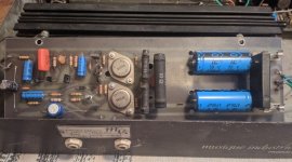
So how many of your transistors failed? Usually output transistor failure stops destroying parts at the driver, predriver, or VAS stage? The temp sensor transistor and diodes can be blown too. Replacing all transistors is not usual. More common is replacing all the electrolytic capacitors, and most of the ones in your picture are axial, which means to me probably very old.
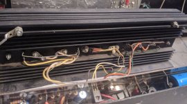
This Musique Industry 1945? is a bit odd with 2n3055 drivers? on board and 4 output transistors on the heat sink. Maybe the configuration is as Mr Fahey posted, the acoustic control 361, with the 2n3055 on pcb as drivers. But your predrivers are TO202 packages instead of TO5 40409/40410.
Somebody that ran sims on the ST120 with models of 2n3055, found that Harmonic Distortion was lower with TIP3055 which is a 4 mhz Ft part instead of 800 khz. I had no surviving 40411 so my ST120 runs with NTE60 copies of MJ15003, and is not high frequency limited with the 40409/40410 drivers. You may wish to replace your output transistors and drivers with something faster for better sound. MJ15015, MJ15003, or even MJ21194. If you do that, those can oscillate. The cure is putting a 10 ohm >=1 watt resistor in the base line from driver to output transistor. I put mine in the wire from the pcb to the transistors on the heat sink, flying out in the air. Did it to provide something to burn up instead of expensive drivers etc, but I've had no oscillation problems. Mooly had oscillation problems on his old 2n3055 amp with faster OT's and put the 10 ohm resistors in specifically to stop the oscillation.
Last edited:
well it's a strange amp...I find the gain test at 2 v or 9 v of a tester to be rather uninformative. Transistors stressed by breakdown of the output transistors fail a Vceo test more reliably, which takes at least 12 v to cause problems in 50 v or higher parts. When I checked stressed transistors in my power amp, some passed a double diode test with the ohms scale @ 2 v, but would blow the tops off under rail voltage. A later check with a 12 v power supply series a 47k resistor and a milliamp scale, proved that some of the ones that passed the diode test would pass the full .25 ma c to e, indicating that only the resistor was holding off the voltage.
So how many of your transistors failed? Usually output transistor failure stops destroying parts at the driver, predriver, or VAS stage? The temp sensor transistor and diodes can be blown too. Replacing all transistors is not usual. More common is replacing all the electrolytic capacitors, and most of the ones in your picture are axial, which means to me probably very old.
This Musique Industry 1945? is a bit odd with 2n3055 drivers? on board and 4 output transistors on the heat sink. Maybe the configuration is as Mr Fahey posted, the acoustic control 361, with the 2n3055 on pcb as drivers. But your predrivers are TO202 packages instead of TO5 40409/40410.
Somebody that ran sims on the ST120 with models of 2n3055, found that Harmonic Distortion was lower with TIP3055 which is a 4 mhz Ft part instead of 800 khz. I had no surviving 40411 so my ST120 runs with NTE60 copies of MJ15003, and is not high frequency limited with the 40409/40410 drivers. You may wish to replace your output transistors and drivers with something faster for better sound. MJ15015, MJ15003, or even MJ21194. If you do that, those can oscillate. The cure is putting a 10 ohm >=1 watt resistor in the base line from driver to output transistor. I put mine in the wire from the pcb to the transistors on the heat sink, flying out in the air. Did it to provide something to burn up instead of expensive drivers etc, but I've had no oscillation problems. Mooly had oscillation problems on his old 2n3055 amp with faster OT's and put the 10 ohm resistors in specifically to stop the oscillation.
so maybe i have bad transistors that still pass the test... i think i'm gonna give up !
ok, one last try...
power section : (4 2N3055 push pull )
now i have 20mV on one 0.25R, and 10mv on the other.
If i'm correct that's 80mA for one pair of 2N3055 (40ma each)
and 40mA for the other pair (20mA each)
Seems like a bad balance ? how much should i target ?
and for the driver section : 2x2N3055
0,6v on one 100R that's 6mA
0,9v on the other 100R that's 10mA
Last edited:
True on bandwidth, and maybe on linearity or Hfe, but definitely not on robustness.Of course all this is moot as newer devices outperform all those old 'homos'.
I have been making Guitar/Bass amplifiers since 1969, always using 2N3055H , more than 14000 amps today, the first 8000 or 10000 using them.
When major manufacturers switched to Epitaxials, I found them weak under grueling stage conditions so I digged deeper and deeper to get the "homos".
My last batch was some 2000 of them made by USHA, an obscure "Made in India" manufacturer with impressively robust devices.
Yes, I measured them, still do, only guarantee to know what am I really getting.
After a while I found USHA was an Indian *Military* factory, which they setup to supply their Armed forces, go figure.
When those run out around 2004 I started using ST ones ... they blew like firecrackers, instant 20% or higher failure rate .... unusable.
Mind you, bought in bulk straight from ARROW or AVNET distributors, in original cartons with all Factory codes, so no fakes.
But Engineers there told me: "in the old days, competition was based on quality, people often paid premium price for premium performance, so old transistors *regularly* exceeded published specs. Today it´s cutthroat price competition, so they *just* meet datasheet specs and not an iota more"
Plus Epitaxial being faster but weaker than Hometaxial.
I also used 2N3773 (again Hometaxial) in my popular 300W Bass amps, until fakes overtook the market and were again unusable.
Last trusty supplier was Mospec, until sellers started getting fake ones too.
Out transistor idle current, okay. 80 ma is not dangerous if you have good sized heat sinks.power section : (4 2N3055 push pull )
now i have 20mV on one 0.25R, and 10mv on the other.
If i'm correct that's 80mA for one pair of 2N3055 (40ma each)
and 40mA for the other pair (20mA each)
Seems like a bad balance ? how much should i target ?
and for the driver section : 2x2N3055
0,6v on one 100R that's 6mA
0,9v on the other 100R that's 10mA
The drivers, something is probably wrong in the preceding section or sections. Go looking up there for source of unbalance in drivers. 6 & 10 ma are not dangerous, but your VAS should balance out to the middle. May be a pot wiper, or even need a balance pot. No schematic, we're guessing.
As I said for 2n3055 On semi MJ15015 from an authorized distributor is your friend. Not using farnell, RS, mouser, digikey reichert? Even using those, did the parts go through customs where fleet fingers may substitute trash for real parts? Test every transistor for Vce breakdown current as detailed previously. At least at 12 v. UPS here is reliable since they have cameras everywhere & track everybody's every minute. Wasn't true in the early 80's.
Last edited:
is it ok to have 80mA on one power side and 40mA on the other?Out transistor idle current, okay. 80 ma is not dangerous if you have good sized heat sinks.
The drivers, something is probably wrong in the preceding section or sections. Go looking up there for source of unbalance in drivers. 6 & 10 ma are not dangerous, but your VAS should balance out to the middle. May be a pot wiper, or even need a balance pot. No schematic, we're guessing.
As I said for 2n3055 On semi MJ15015 from an authorized distributor is your friend. Not using farnell, RS, mouser, digikey reichert? Even using those, did the parts go through customs where fleet fingers may substitute trash for real parts? Test every transistor for Vce breakdown current as detailed previously. At least at 12 v. UPS here is reliable since they have cameras everywhere & track everybody's every minute. Wasn't true in the early 80's.
Yes, both will amply cover up crossover distortion. Excess current over 40 ma comes out as heat. Even 20 ma is pretty good at covering crossover distortion.
2mA is good enough to cover crossover distortion with modern epitaxials. In the old days it took more, especially considering the balance wasn’t as good between parallel units. With those old rugged devices balance just didn’t matter as much. But the harder you push them, the better the balance got, typically. Might be 20 and 40 mA at quiescent, but close to 3 amps each when clipping. The high base spreading resistance of the homo’s did this for you.
For what it’s worth I’ve had pretty good luck over the years with Mospec. The 3773’s and 6609’s they make were always the newer epitaxial type. I’ve cut ‘em open, and the die is about the right size for 150 watt, they have a real copper heat spreader, sintered die attach, and it is mounted at 45 degrees like it’s supposed to be. They do use white silicone, though. They used to measure exactly like an old 1980-era Motorola. Mospec 2N6609’s that I’ve bought *recently* from Newark however, measure exactly like an ON MJ15004. So did the last batch of Moto 6609’s I bought when they announced EOL. At $3.13 each I figured they would be worth a try, to see if they re as good as the ones from the early 90’s. That saves my A-stock MJ15025 stash for critical applications.
If you’re replacing homo 3055’s these days, don’t have any old stash to work from, and can’t afford to take any chances or experiment, the only thing that makes sense to use are ON MJ15024. For supply voltages up to +/-60V it is the most rugged thing out there. If you push higher in voltage, the 2119x makes more sense. It is as rugged as an old 3055, perhaps more, and will always stand off more voltage. But it takes a die about 6 times the size to do it.
That is a very primitive amp. Apex AX6 would be better if you feel like making boards.
Which side output transistors, the plus side or the minus side have the 80 ma bias current? Since you got rid of the MPSU06 that might blow up with more current, you can inject some current in the Q3 Q5 R13 predriver input stack to move it one side or the other. If the negative side R19 has hotter idle current than R18 plus side, I'd put 270 ohm 1/2 W series a 5 k pot parallel R19 and pull the whole stack up a little.
You may want to put a heat sink on the MJE340 Q4. 1.5 cm of scrap window frame with holes drilled in it works fine, if you can't buy one without a E8 UPS fee. If you live in Ilse-de-france you may have a local distributor that would cost only a Metro ride. Don't forget a 3 mm or 4 mm screw & nut to hold it on, and heat sink compound is useful if you don't have to pay E10 for it. this position, VAS is not usually heat sinked, but people that fix amps find VAS & drivers blown up a lot.
Connect the new pot wiper to one end. Adjust the RV1 to lower currents to 5 ma & 10 ma then adjust new pot to center it. If RV1 won't lower the idle current that much then short the wiper to one end, and or decrease R6 and or R7 a little bit. You can parallel a resistor like 10k or 4.7k to R6 or R7 instead of pulling them out of the board to lower the value. (true of any resistor that needs value lowered).
Don't forget to replace each wire from driver pair to output transistor bases with a 10 ohm 1 watt or higher resistor. This "base stopper" is what mooly recommends for old amps that have slow homotaxial 2n3055 replaced by modern parts that are 8 times faster. Else the outputs might oscillate. I put a 8 turn coil in the wire running from heat sense transistor Q3 back to the base of driver Q6 Q7 for the same reason. Salvaged the coil out of a dead PCAT power supply, but I think it may be about a microhenry.
Last edited:
another try with my audio probe... good signal injected at F and B
sound is ok at base of Q1
sound is already badly distorted at base of Q2 !!!
and probing the 2 2N3055 drivers : there's a big difference in volume + sound is really bad
sound is ok at base of Q1
sound is already badly distorted at base of Q2 !!!
and probing the 2 2N3055 drivers : there's a big difference in volume + sound is really bad
If the amp is old then its usually electrolytic's that go first.
If the transistors really have gone then I found ebay to be last resort for finding obsolete stuff.
If the transistors really have gone then I found ebay to be last resort for finding obsolete stuff.
- Home
- Amplifiers
- Solid State
- Transistors replacement to repair a vintage SS amp