Start at the very beginning.another try with my audio probe... good signal injected at F and B
sound is ok at base of Q1
sound is already badly distorted at base of Q2 !!!
What is the DC voltage of e,b,c of Q1?
Changed parts by amateurs usually inject some bad solder joints.
C2 or C3 could be shorted too; should have DC voltage across them. French film caps of 1966, SOA? or some brand had a very bad reputation for leakage. Couldn't spray the metal on the film correctly.
If b & e of Q1 are same voltage, MPSA55 is a cheap version of MPSA56 available everywhere. EBC subs, MPS8599, 2n5400, 5n5401 2n 5322 2n5415. Too much voltage for 2n2907 2n2905. You could put a BC556 in backwards, flat on opposite side of the flat on the MPSA55. BC557 558 559 BC560 are too low in voltage rating.
Last edited:
Q1 : vb=4mv
vc=-43.8v
ve=350mV
1.7v across c3
1.2v across c2
Q2:
vb=-43.8
vc=-2.6
ve=-44.6
vc=-43.8v
ve=350mV
1.7v across c3
1.2v across c2
Q2:
vb=-43.8
vc=-2.6
ve=-44.6
Last edited:
There is not enough voltage b-e on Q1 for it to turn on. Look at voltage at + of C6 (which should be 4 mv same as b of Q1) and + of C9 which should be fairly positive. May be bad solder joint in that string. Or buzz the string. Voltage across R10 should tell you if the pullup string is bad or the Q1 transistor b-e joint is leaking.
If Q1 was turned on voltage on C3 would be more like 3.5 the print shows (assuming negative rail is -48).
If Q1 was turned on voltage on C3 would be more like 3.5 the print shows (assuming negative rail is -48).
i took a direct mesure of Vbe on q1 and it's 495mA. not enough?There is not enough voltage b-e on Q1 for it to turn on. Look at voltage at + of C6 (which should be 4 mv same as b of Q1) and + of C9 which should be fairly positive. May be bad solder joint in that string. Or buzz the string. Voltage across R10 should tell you if the pullup string is bad or the Q1 transistor b-e joint is leaking.
If Q1 was turned on voltage on C3 would be more like 3.5 the print shows (assuming negative rail is -48).
V+ of C6 is the same as Q1 Ve (about 500ma), not the same as b of Q1 - but looking at the schem its ok?
theres no voltage drop across R10
V+ of C9 is the same, 500ma
Last edited:
Vbe of .495 is pretty light. .6 to .7 is usual. Voltage drop across R10 zero indicates it is not C2 leaking.
Is V @ C of Q6 +48? Pin 1 of Q6 is supposed to be .69 v. C9 is not a 25 v cap to hold off .5 v.
BTW voltages are in millivolts, not milliamps.
Is centerline of amp, negative of C10, about middle of +48 -48 rails? Something is weird, ring of output jack only connects to centerline through 4.7 k . they are driving tip of "haut parleur" with centerline, what ever that means. High Speech 4 ohms? you can drive ring or tip, but having one tip and one ring driven is weird.
Last edited:
i measured voltage drop across R10 and R11. ohms law tells me i have 0,018mA current in that line ! so it means Q1 is closed ?Vbe of .495 is pretty light. .6 to .7 is usual. Voltage drop across R10 zero indicates it is not C2 leaking.
Is V @ C of Q6 +48? Pin 1 of Q6 is supposed to be .69 v. C9 is not a 25 v cap to hold off .5 v.
BTW voltages are in millivolts, not milliamps.
Is centerline of amp, negative of C10, about middle of +48 -48 rails? Something is weird, ring of output jack only connects to centerline through 4.7 k . they are driving tip of "haut parleur" with centerline, what ever that means. you can drive ring or tip, but having one tip and one ring driven is weird.
What is setting the biasing of Q1 ?
Q6 :
Vb=0,69V
Vc=46v
Ve=0,2Vb
C10 : Vneg = -0,1V (Vpos = 36V)
about output : "haut parleur" means speaker in french. "haut parleur" is the speaker output.
"OUTPUT" is an atenuated output for studio use
Last edited:
Q6 is not turned on either, 0.49 v b-e. That low value at e of Q6 is preventing Q1 from turning on.
check centerline, - of C10, is center of power supply. If plus 46, to minus rail should be 46 also. Similar AX6 has a DC feedback circuit to do this, but this doesn't have one that I can see.
You don't have a scope to check for oscillation. You don't have a analog VOM which can spot it also. I'd say at this point, put a 1k resistor parallel to R13, series a 4.7k pot with wiper tied to one end. So that stack can go from 1000 to 5700 ohms parallel the 3.9k of R13. Adjust pot until e of Q6 gets to 0.69 v as shown. That may turn on Q1.
Sorry for delay, I've been watching news of Iowa caucus result.
"high speech" = speaker. Interesting.
Last edited:
"Similar AX6 has a DC feedback circuit to keep the centerline centered."
Instead of the pot parallel R13 in post 47, you might try a 14k or 15 k from negative of C10 to emitter of Q1. This appears analogous to what there is on the AX6 that makes it work.
Actually, just changing the whole structure of Q1 Q2 Q4 to be exactly like apex ax6 is more secure, since those actually work. The triple output and vbe multiplier should not make much difference. The vbe multiplier is like AX8 anyway.
musique industry 915 higher resistor values may be more appropriate to +-48 rails instead of +70 v I have my AX6 running on.
Last edited:
thanks for your help.
i made a confusion between q6 and q8. my readings of q6 are wrong. i'll mesure again tonight !
i do have a scope and a frequency generator
i made a confusion between q6 and q8. my readings of q6 are wrong. i'll mesure again tonight !
i do have a scope and a frequency generator
Can you also post the rest of thne schematics?i found the schematics !
only difference is the power transistors are 2n3055
I am interested in the preamp(s), EQ, possible distortion or reverb, etc.
SS Guitar amps use basically same power amps (meaning flat and high power, not much variation there) , the "special sauce" is added in the Preamps, which are all very different, depending on brand.
Thanks in advance.
Also look at centerline (junction of R18 R19 or negative of C10) with scope to make sure channel is not oscillating. Sweep at 1 usec/div , vertical at 10 mv/div, amp input shorted.i made a confusion between q6 and q8. my readings of q6 are wrong. i'll mesure again tonight !
i do have a scope
mmmQ6 is not turned on either, 0.49 v b-e. That low value at e of Q6 is preventing Q1 from turning on.
check centerline, - of C10, is center of power supply. If plus 46, to minus rail should be 46 also. Similar AX6 has a DC feedback circuit to do this, but this doesn't have one that I can see.
You don't have a scope to check for oscillation. You don't have a analog VOM which can spot it also. I'd say at this point, put a 1k resistor parallel to R13, series a 4.7k pot with wiper tied to one end. So that stack can go from 1000 to 5700 ohms parallel the 3.9k of R13. Adjust pot until e of Q6 gets to 0.69 v as shown. That may turn on Q1.
Sorry for delay, I've been watching news of Iowa caucus result.
"high speech" = speaker. Interesting.
strange
look at the schematics : pin 1 of q6=0,69V pin 3 of Q6= 1,22v
so Vbe of Q6 = 0,530V on the schematics !
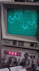
some signals, Q1, E and C... weird... E is fixed, C keeps moving...
Attachments
Last edited:
2 mv oscillation is not much of a problem. If just fuzz instead of a .5-20 mhz sine wave, it is just noise.
If designer put that voltages on print, that is what they want.
Check opposite side transistors b-c to see if that is cause of the plus and minus imbalance. You still have 40 ma idle OT current one side, 80 ma the other? is the plus side the 40 ma side, r18?
If Q1 still won't turn on (make sine waves out collector when input is a sine wave) then put balancing 15 k in to center which was in post 49 maybe?
You should be able to trace sine wave through with a scope up to the emitter follows (output transistors) to see where the sine wave starts to look bad. That stage is the problem. If Q1 makes a sine wave, then the bad sound from the sound probe is the sound probe. I was assuming Q1 c was a flat bottom half-sine wave due to almost shut off condition.
Off to service an organ, it is early afternoon here. Back about 4 hours.
Last edited:
Waveforms posted after I posted #54.
Those waveforms are nasty. Flat bottom waves, half sines as I said earlier. Plus the points aren't sine wave at all, apparently happen sometimes since they are faint.
Loose solder joint? Excess high frequencies (the points) can be caused by capacitors used as a differentiator in the feedback path. If the electrolytic caps are all new, I'd take a meter to, or change out, C2, c3, c4.
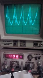
See if Q1 has same thing or nice sinewaves.
& look at Q2 & Q4 to see if you have whole sine waveforms there. Half waveforms might be okay for only the upper half of the wave. Not the points on top.
Those waveforms are nasty. Flat bottom waves, half sines as I said earlier. Plus the points aren't sine wave at all, apparently happen sometimes since they are faint.
Loose solder joint? Excess high frequencies (the points) can be caused by capacitors used as a differentiator in the feedback path. If the electrolytic caps are all new, I'd take a meter to, or change out, C2, c3, c4.
See if Q1 has same thing or nice sinewaves.
& look at Q2 & Q4 to see if you have whole sine waveforms there. Half waveforms might be okay for only the upper half of the wave. Not the points on top.
Last edited:
the waveforms are Q1's
any chance q1 is malfunctioning?
i already tried to replace the cerami caps... might try again
any chance q1 is malfunctioning?
i already tried to replace the cerami caps... might try again
Thought the waveforms were Q6. Feedback differentiator Q6 to Q1 could cause the pointy peaks in Q6, but Q1 has no local feedback.
Yes Q1 could be bad but very strange distortion. Replacements listed in post 46.
You still haven't reported if Centerline (minus of Q10) is centered +-46 from power supplies with no signal. If not pick up a 15 k resistor while you are shopping, plus a 1 k resistor and a 4.7k potentiometer.
The known fault of a brand of french caps 1966 are film caps. Most other brands of film caps 1966 as mallory, sprague, goodall, were highly reliable and don't age at low voltages compared to rated voltage. Film caps will short at 2x rated voltage if rail voltage gets loose from shorted output transistors.
Last edited:
Thanks a lot 🙂here are the preamp schematics
A small detail: on the EQ schematic, C8 must be connected to Q3 collector, not its emitter.
Later will check all 3 schematics to see whether there is anothes small detail such as that one.
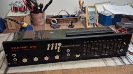
"Some day", after this problem is sorted, it would be nice to have a full frontal picture of this amp, I vaguely remember ads in the "Sono" magazine.
We are talking mid 70´s or so.
Also remember the "French Marshall" amps, 😱 , although not the brand. 🙁
- Home
- Amplifiers
- Solid State
- Transistors replacement to repair a vintage SS amp