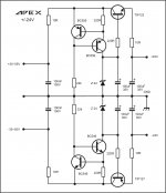
Apex proposed a circuit board in post 18
A-class Preamp PSU
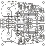
i have attached a file from post 20. is it ok? size is 80X77.5 mm
Attachments

It is a simple ccs driven Zener reference with emitter follower, probably not enough "high end".
It is a simple ccs driven Zener reference with emitter follower, probably not enough "high end".
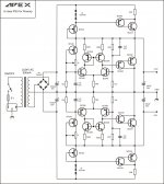
what about this design?
Attachments
The schematic in the first post will be higher performance (and gives transformer specs).
Not sure what that board layout goes with....
Not sure what that board layout goes with....
oh ok I see 500mA transformer got it, yes this layout is actually the one that goes with the first post I think I'm gonna make this one but sadly those BF245A are obsolete and hard to find unless a equivalent can change this part number 🙁
this layout goes with this schematic yes
I found this part number BF256B is this one can be use instead of BF245A?
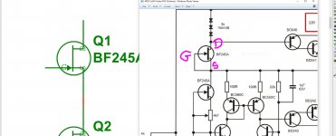
one more thing the original schematic does not show the pins identification I assume that is like this right 😕
this layout goes with this schematic yes
I found this part number BF256B is this one can be use instead of BF245A?
one more thing the original schematic does not show the pins identification I assume that is like this right 😕
Attachments

Last edited:
Those JFETs are just used as a current source, so you don't need anything exotic, but you do want a similar Idss and low-noise. The BF256B meets the first criteria, but the datasheet makes no mention of noise.
What about a 2n5457?
(Note: you'll need to compare pinouts of any replacements as they aren't all the same.)
What about a 2n5457?
(Note: you'll need to compare pinouts of any replacements as they aren't all the same.)
Those JFETs are just used as a current source, so you don't need anything exotic, but you do want a similar Idss and low-noise. The BF256B meets the first criteria, but the datasheet makes no mention of noise.
What about a 2n5457?
(Note: you'll need to compare pinouts of any replacements as they aren't all the same.)
oh ok I'm gonna check the 2N5457 and yes I'm aware of pins can be different if I clone this layout and avoid errors
I know Mr. Miles must be occupied I hope he can identified the pins of those BF245A on the schematic so then I can modified the layout to accept ones that are available to purchase

I wrote about the BF245A replacement here before I think - use any small signal n-channel JFet.
you gotta be kidding...there's no need for any regulator in a class a preamp...a very simplistic capacitor multiplier will do the job equally well for any high end audio preamplifier.The most complicated design needed will probably have 6 transistors for both rails, but nothing else , no matter how complicated it may be, can do a better job as long as you're making use of capacitors to filter, decouple and stabilize that exquisite regulator anyway.Audio world is not full of CERN's photon or nuclear measuring systems.Topics like these make me really mad because when i started electronics i thought that electronics designers do anything they do for a reason, a TECHNICAL reason...It took me more than a decade to find out how many hoaxes i fully believed at start are floating around disguised in technical subtilty clothes.
Class A amplification means almost constant current draw. no real transients are found in a class A amp , no matter the power..
Class A amplification means almost constant current draw. no real transients are found in a class A amp , no matter the power..
Last edited:
I wrote about the BF245A replacement here before I think - use any small signal n-channel JFet.
ok I'll check that thanks 🙂
you gotta be kidding...there's no need for any regulator in a class a preamp...a very simplistic capacitor multiplier will do the job equally well for any high end audio preamplifier.The most complicated design needed will probably have 6 transistors for both rails, but nothing else , no matter how complicated it may be, can do a better job as long as you're making use of capacitors to filter, decouple and stabilize that exquisite regulator anyway.Audio world is not full of CERN's photon or nuclear measuring systems.Topics like these make me really mad because when i started electronics i thought that electronics designers do anything they do for a reason, a TECHNICAL reason...It took me more than a decade to find out how many hoaxes i fully believed at start are floating around disguised in technical subtilty clothes.
do you have a circuit that can then I follow? if not regulation is need it then I can go for that option too
A simplistic capacitance multiplier has issues too (for instance, when the supply voltage drops). And you're never going to get the output impedance you can with a regulator.
(The class-A constant-current-draw argument only holds for single-rail topologies. While the total current draw is nearly constant for a dual-rail design, the draw from each individual rail has twice the variance of a class-B design.)
You can get better ripple rejection and output impedance from a regulator. Yes, it will be more complex. And it will have feedback, so stability needs to be ensured. A series regulator will also need to dump a lot more heat -- and if it's a shunt then bucket loads more heat.
What will work best depends on what your design goals are.
There's a good discussion here: Supply Filtering and why Capacitance Multipliers are NOT the Answer.
Attachments
Yeah right...and the first two guys talking there are some of the the most expensive sellers of "high endish" useless toys in the diy world...today, if you have an Audio Precision to back your designs you can tell anything as a rule of thumb, but the rules of thumbs are many!A simplistic capacitance multiplier has issues too (for instance, when the supply voltage drops). And you're never going to get the output impedance you can with a regulator.
(The class-A constant-current-draw argument only holds for single-rail topologies. While the total current draw is nearly constant for a dual-rail design, the draw from each individual rail has twice the variance of a class-B design.)
You can get better ripple rejection and output impedance from a regulator. Yes, it will be more complex. And it will have feedback, so stability needs to be ensured. A series regulator will also need to dump a lot more heat -- and if it's a shunt then bucket loads more heat.
What will work best depends on what your design goals are.
There's a good discussion here: Supply Filtering and why Capacitance Multipliers are NOT the Answer.
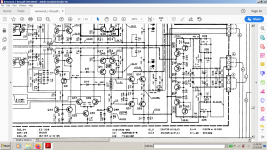
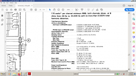
Well I just posted the most advanced phono preamp inside the most advanced integrated receiver ever made commercial by the same team that gave birth to Accuphase(Kenwood+ Kensonic). The input differential section by itself takes 34ma...
I'm talking about this:
Kenwood L-02A on thevintageknob.org
L-02A KENWOOD - HiFi-Do McIntosh/JBL/audio-technica/Jeff Rowland/Accuphase
Yeah, i saw it's full of cascodes with not so great PSRR while placed into a 2x 170w RMS class ab power amp ...
Is it up to you expectation?
Attachments
Last edited:
Ummm... that Kenwood is using a series regulator, not a c-multiplier.
It's not a differential series regulator with global feedback -- the Kenwood employs only local feedback through emitter degeneration. Is it the differential topology you take issue with?
It's not a differential series regulator with global feedback -- the Kenwood employs only local feedback through emitter degeneration. Is it the differential topology you take issue with?
Yeah, i saw it's full of cascodes with not so great PSRR while placed into a 2x 170w RMS class ab power amp ...
Check out the circuit they're driving the cascodes from. Is that some sort of current-mirror voltage stabiliser?
So it's a very basic one!!!Ummm... that Kenwood is using a series regulator, not a c-multiplier.
It's not a differential series regulator with global feedback -- the Kenwood employs only local feedback through emitter degeneration. Is it the differential topology you take issue with?
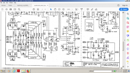
That was my answer for you ...the previous post had the capacitor multiplier article on ESP site. I can't count the number of low noise preamps supplied by a simple c-multiplier i saw in real life high quality equipment where they measure less than 0.003thd+IMD distortions over the full audio spectrum...
Now you have the most complicated c-multiplier i have ever seen following a faster regulator 🙂
Attachments
Last edited:
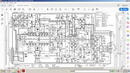
so the input is a switched bjt or fet input cascoded...they use bjt input for mc cartridges and fet input for mm cart.They have a relay that switches the source or emitters to the 17ma cascoded current source.Check out the circuit they're driving the cascodes from. Is that some sort of current-mirror voltage stabiliser?
- Home
- Amplifiers
- Power Supplies
- A-class Preamp PSU