Just see from the simulation the currents they run multiplied with 4 x 24v .In my simulations the models never care about the max dissipation power product .Of course , changing them might have an effect on the overall linearity...i suppose you know better those aspects.
Last edited:
since this is a subject about the A-class Preamp PSU I'm gonna leave this section and go to the the ones that disgust about this Apex P30 preamp circuit I don't want to confuse people and keep the subject of this A-class Preamp PSU here
by the comments of you guys I came to the conclusion that is not really need it is a good thing for me because save me money, yes dreamth I will check that "linearity" among other things,so I'm gonna close this section for me and go to the Apex P30 and continue with them
maybe I will make this A-class Preamp PSU just for curiosity in the future
Best Regards
Juan
I don't want to confuse people and keep the subject of this A-class Preamp PSU here
...
maybe I will make this A-class Preamp PSU just for curiosity in the future
...
Best Regards
Juan
I agree. This is one of the more useful threads about parallel / shunt regulators.
Leave it as it is.
Supply regulators like this can be made in a simpler but efficient manner
or even more complicated. It is, as always, a matter of taste.
That is extreme values (2x24V max), adjusting on 2x18V is also possible.
Regards
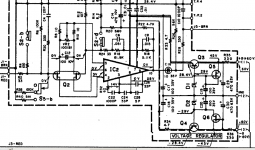
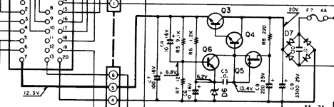
Just 80's "low fi commercial" stuff ...PSU for preamps with Serial Regulator.
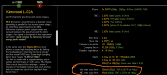
Kenwood KA-1000 on thevintageknob.org
Kenwood KA-2200 on thevintageknob.org
Kenwood L-01A on thevintageknob.org
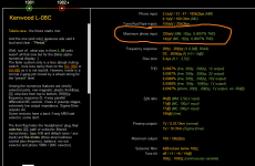
Kenwood L-08C on thevintageknob.org
Attachments

Last edited:
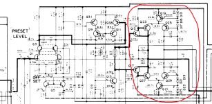
I put all the necessary links:What's that last one? It's the Hitachi topology again, but with Sziklai outputs.
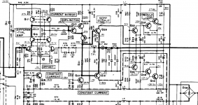
Kenwood l-08c preamp unit. I added the input max headroom printscreen at which it holds 0.007%THD...You find all the manuals on electrotanya and hifiengine.In Romania i can't acces hifiengine...but you can in Ireland.

I am not sure why you constantly would want to post random snippets of,Just 80's "low fi commercial" stuff ...
mainly Japanese, amplifier circuits, here and elsewhere in this forum.
Most of the time these are shown without source or description of their origin.
If it is of any interest everybody will be able to find these schematics themselves.
Where is the relation to the topic of this thread ?
On the other hand, if you want to teach us something, please analyse and
describe the circuits and tell why they may be important to others.
This is a DIY Audio Forum, no commercial schematic collection (I admit I initiated
an Accuphase circuit thread, but strictly for repair purpose). This particular thread
here started as a description of a nice discrete shunt regulator from an acknowledged
master. If you can contribute to that we will love it.
This is not a random schematic peep show - or start your own thread for that.
I didn't know we are forbidden to quote real masters like those who actually made Accuphase or their commercial designs, yet we have to agree that a wrongly chosen topic name has to be accepted .If i get in your beloved Accuphase repair topic should i wait for your approval to say anything too?I am not sure why you constantly would want to post random snippets of,
mainly Japanese, amplifier circuits, here and elsewhere in this forum.
This is a DIY Audio Forum, no commercial schematic collection (I admit I initiated
an Accuphase circuit thread, but strictly for repair purpose). This particular thread
here started as a description of a nice discrete shunt regulator from an acknowledged
master. If you can contribute to that we will love it.
This is not a random schematic peep show - or start your own thread for that.
What do you think: should we talk about Lamborghini engine sound effects here now that the topic's name is about something else than it describes?
Are you so disgusted by Kenwood's commercial designs that made history ?
Last edited:
If you want to quote : tell the name of the amp or master.
I am not sure what schematics you post since you do not care to describe it.
Bought my first Kensonic amp 45 years ago ..
I am not sure what schematics you post since you do not care to describe it.
Bought my first Kensonic amp 45 years ago ..
https://www.diyaudio.com/forums/power-supplies/164365-class-preamp-psu-23.html#post6057468If you want to quote : tell the name of the amp or master.
I am not sure what schematics you post since you do not care to describe it.
Bought my first Kensonic amp 45 years ago ..
Do you have eyesight problems?
Well, personal attacks will not help.
Do a survey of all the useless stuff you post.
At least this last time there is a hint to the source.
Do a survey of all the useless stuff you post.
At least this last time there is a hint to the source.
I didn't show the manufacturer name in some topics where some jokers claiming to have discovered current feedback amplifiers used Accuphase or Mark Levinson designs to back their absolute "authority" as a Budha kind of audio guru ...Well, personal attacks will not help.
Do a survey of all the useless stuff you post.
At least this last time there is a hint to the source.
classic layout to a modern one
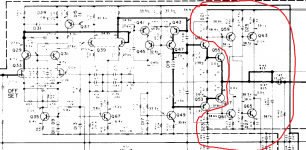
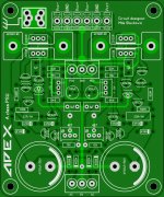
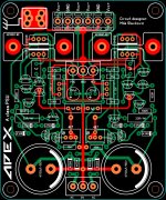
hi guys I decide to just make the layout same as the original but with more options of connectivity and I re-arrange the transistors to share a heat sink
"yes I know I got the floating GND I will used that thank you"
not many people like to use this time of circuit but I just want to try out here is the layout image
Attachments

oh I see what you mean yes they are this top copper traces that might be compromise yes, the heatsink is gonna need a separation for the top PCB I guess
the red traces are top copper traces the green ones are bottom copper traces
the red traces are top copper traces the green ones are bottom copper traces
Attachments


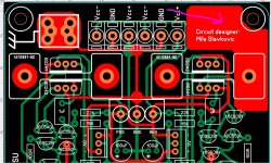
If you insert space between your heatsink and the board then you're relying on the bottom pad (plus whatever small amount of solder wicks to the top) to hold it. That's a pretty tall heatsink for that.
I'd move the top copper traces a little so they aren't under the heatsink, and then mount the heatsink flush to the board.
I'd move the top copper traces a little so they aren't under the heatsink, and then mount the heatsink flush to the board.
- Home
- Amplifiers
- Power Supplies
- A-class Preamp PSU