Fetamp, its a simple calculation that you could do yourself. 68V in, 33V zener, required voltage drop 35V, current through resistor 2mA, resistor value 35/0.002=17.5k. Nearest preferred value 18k, 0.5W
Thanks a lot Chalky.....I’m in final stage of two boards assembling and will post updates
Fingers crossed here.
Remember bulb in series with transformer, or resistors in in series with rail, think a 68-100 ohm.
Remember bulb in series with transformer, or resistors in in series with rail, think a 68-100 ohm.
Fingers crossed here.
Remember bulb in series with transformer, or resistors in in series with rail, think a 68-100 ohm.
Thanks amplidude...I adjusted voltage across R41 for 0.5 v before installing power tubes.Do I further need bulb in series ?
hi.
i just copied from papers the startup. if its drawing 1 amp or above it might be oscillating, check with scope anyway on output.
Bryston 4B-SST debugging instructions:
1. Ensure that all components are of acceptable quality and properly installed;
2. Ensure that all solder joints are free of false soldering and short circuits;
3. Do not install the power tube before power-on and the transformer is connected in series. 60‐100W
Incandescent bulbs, especially all SGND and PGND on the board
Use the GND of the large reservoir;
4. Test whether +/‐V2A (ie C26, C30 capacitor voltage) is after power-on.
+/‐33V or so (all between 31-33V is normal);
5, adjust VR1, the measured output OUT is close to 0V (+/- 10mV);
6. Adjust VR2 and measure R38; R39; R40; R41 The voltage across R41 is the minimum value, and the range is about 0.5‐0.58V (if there is an oscilloscope to test the signal channel, there is no problem);
7, properly install the power tube (must connect the incandescent bulbs in series), adjust VR2
Make Q19 current about 5mA; after removing the bulb, adjust VR2 again to make Q19 current 70-80mA (ie, the voltage across R45 is 23-25mV);
8. Re-adjust VR1 to make the output OUT close to 0V (within +/-10mV);
Hi fetamp.Thanks amplidude...I adjusted voltage across R41 for 0.5 v before installing power tubes.Do I further need bulb in series ?
How did your initial startup go? I hope well, and no smoke.
Hi fetamp.
How did your initial startup go? I hope well, and no smoke.
Hi...amplidude thanks for you being with me...ha...ha...no smoke work nicely with +/-68v,the only problem is comparatively low output than other types of PCBs.as advise by you and chalky input power increased but no significant improvement in output?.
Any other suggestions? Is it normal for this type output stage design ?and please explain why there are different bias voltages and different voltages across emitter resistors?
Thanks
Easy answer first. There will always be a small amount of variation in voltage across the emitter resistors because the current sharing is never perfect due to differing transistor characteristics. With +/-68V supplies you should be able to blow your socks off with a couple of volts of input. Do you have any way of measuring the output voltage, preferably into an 8ohm dummy load, but unloaded will do?
Glad it worked, or almost worked.
Strange with your gain issue, but do like chalky said, measure your output
Strange with your gain issue, but do like chalky said, measure your output
Easy answer first. There will always be a small amount of variation in voltage across the emitter resistors because the current sharing is never perfect due to differing transistor characteristics. With +/-68V supplies you should be able to blow your socks off with a couple of volts of input. Do you have any way of measuring the output voltage, preferably into an 8ohm dummy load, but unloaded will do?
Thanks chalky....i have not got signal generator ,oscilloscope with me.i watched several videos that demonstrating gain check in a AMP,.Is it ok to check gain with normal music input and output to 8 ohm speaker?
Glad it worked, or almost worked.
Strange with your gain issue, but do like chalky said, measure your output
Hi...amplidude few clicks of AMP
Attachments
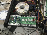
Do check that you have the correct voltages on regulators also, both input and output board
Around 30v in main board regulator output?
Check also that all the earths are properly connected.
Chalky please let me know purpose of using small caps in between output transistors.?...all grounds are ok
Looking good, is the heatsink grounded? Theres a ground on output board up at input.
The small caps between mosfets are buffers, just like Psu caps, they are close to mosfets which is good when high current peaks accure
The small caps between mosfets are buffers, just like Psu caps, they are close to mosfets which is good when high current peaks accure
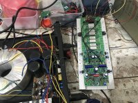
Q1-Q4. Are they correct installed or did you use different transistors than pr bom?
V2÷ V2+ should show around 33 volt from the zener.
One more thing, know your audio source, looks like you bypassed the DC input cap, or is it hiding under connector?
What is driving output board ? It's hard to see but doesn't look like the one from kit.
V2÷ V2+ should show around 33 volt from the zener.
One more thing, know your audio source, looks like you bypassed the DC input cap, or is it hiding under connector?
What is driving output board ? It's hard to see but doesn't look like the one from kit.
Last edited:
Q1-Q4. Are they correct installed or did you use different transistors than pr bom?
V2÷ V2+ should show around 33 volt from the zener.
One more thing, know your audio source, looks like you bypassed the DC input cap, or is it hiding under connector?
What is driving output board ? It's hard to see but doesn't look like the one from kit.
Thanks a lot amplidude...Q1-4 are BC546/56 as suggested by Chalky,
Input cap is there-10uf,input board is not kit one it’s from salvaged power amp.
Amplidude/Chalky please let me know can I use direct audio mixer without input board to drive power board?any pros and cons ?.V2-/V2+ 30v may be problem with zener ...will replace and see.
Well original input board has around a gain of 3 as I remember, I'm not sure a mixer can make it swing full voltage, if you're regulators are close to 33 volt it should work no need for replacing, did you check that the power ground on amp board is connected?
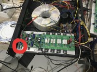
Thanks Amplidude for your reply .....I ordered two mono boards of Bryston input and awaiting it(no space to install long single stereo input board).still worked without grounding pointed by you...will check againPower ground in circle.
Make sure it's connected.
- Home
- Amplifiers
- Solid State
- Bryston 4B SST clone