You mean distrusting measured factual performance. Opinion is what you have, established knowledge is what we have. Nature cannot be fooled.
Facts vary over time as science progresses. Treating science as religion is foolish as the nature of science is not to be "correct", only to observe and collect data,. It makes no claims about anything more than that.
It is less of a field and more of a practice.
In other words, until you know everything, you don't know anything. Educated guesses at best. This applies at every level of life.
Anyway, can I assume that the optimal course of action for an ultra low distortion resistor is a network of high value resistors in huge series/parallel configuration?
I have my own "audio atomic clock", a presumably original design, that I'm finally getting professionally measured next month and I'm curious to know as I goofed up and only put two 0603 10k resistors on board, totally spaced on the whole resistor distortion thing.
Last edited:
Science is all about knowing things and understanding things, with more and more detail and precision and depth. Being correct is everything - ie models need to match experiment or they get junked (or more often improved)
Thats exactly why science isn't a religion, only reality matters in deciding an issue.
Even most observational data isn't fact, its a statistical window onto the facts, often the best we can arrange. Theories and models evolve over time as progress is made, and many get to be regarded as fact with enough evidence and statistical support, but a theory is still a theory even with vast amounts of supporting evidence and no counterexamples.
That said you can trust your life to most of them (you probably do without even realizing as much technology is built upon physical theory) - the evidence is compelling.
Quantum mechanics is a example of when our understanding jumped ahead rapidly as the shortcomings of classical physics in explaining atoms became obvious - reality forced people to deal with non-intuitive complexities of quantum mechanics to understand the small scale. The classical results we re-understood as large scale approximations to quantum behaviour. We still use classical physics all the time, its a (extremelt) good approximation in many situations.
Thats exactly why science isn't a religion, only reality matters in deciding an issue.
No, clearly a trite and nonsensical statement. You can fly to the moon with Newton, but you need Einstein to run a GPS system - doesn't mean Newton is worthless, its an approximation that's often good enough.until you know everything, you don't know anything
No, a fact is a fact (doh). Explanations certainly vary over time though.Facts vary over time as science progresses
Even most observational data isn't fact, its a statistical window onto the facts, often the best we can arrange. Theories and models evolve over time as progress is made, and many get to be regarded as fact with enough evidence and statistical support, but a theory is still a theory even with vast amounts of supporting evidence and no counterexamples.
That said you can trust your life to most of them (you probably do without even realizing as much technology is built upon physical theory) - the evidence is compelling.
Quantum mechanics is a example of when our understanding jumped ahead rapidly as the shortcomings of classical physics in explaining atoms became obvious - reality forced people to deal with non-intuitive complexities of quantum mechanics to understand the small scale. The classical results we re-understood as large scale approximations to quantum behaviour. We still use classical physics all the time, its a (extremelt) good approximation in many situations.
The nature of being correct is not to assume you are correct, it is to let the data form its own solution without bias.. But you can never have infinite data from infinite perspectives on infinite subjects, and everything is interconnected, so you can intrinsically only have guesses.
Being right isn't about knowing everything, it's about understanding what you don't know.
Internally regarding something as knowledge and internally regarding something as fact are two entirely different things.
You have much to learn.
Being right isn't about knowing everything, it's about understanding what you don't know.
Internally regarding something as knowledge and internally regarding something as fact are two entirely different things.
You have much to learn.
Last edited:
I don't think that statement is meaningful or useful, its a soundbite.The nature of being correct is not to assume you are correct
The practical accumulation of knowledge and explanation is the endevour of science. Gaining knowledge and explanation from data is hard work, its struggle and imagination and luck and certainly not about letting the data "form its own solution" - you have to interrogate nature actively, seeking enlightenment and the deep structure within. You can have a guess, you then devise experiments to disprove it, or back it up, and hundreds of people then criticize and interrogate your approach and techniques and data - mistakes need weeding out.
Earlier you said "as the nature of science is not to be "correct", only to observe and collect data" - that's one form of cargo-cult science I think - science seeks to explain and predict, to get under the surface. Collecting data is a necessary but insufficient approach.
Its about questioning nature and unlocking what lies hidden. If you have a theory that matches the known data you next think of a question to ask to discriminate between that theory and another.
For instance: theory: "people can detect 0.01% distortion", experiment: "double blind comparison between 0.0001% and 0.01% distortion signals with N subjects and M trials each" - result is a statistical set of data, apply the standard null hypthesis, publish outcome. Double blind is required as previous experiments show expectation bias is a strong confounding factor in audio comparisons.
You're not understanding what I said at all. Maybe one day.
In any case let's leave it be and not derail the thread.
In any case let's leave it be and not derail the thread.
10 Vishay 1K Ohm 0.01% foil resistors are coming to my mail box today. 2 are going into the test bridge with the 8 Vishay PTF65 thin metal film reference resistors.
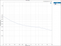
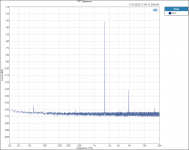
I ran a THD+N (20 volt) sweep, from 20 to 20K with the all PTF65 test bridge, that shows gradually decreasing THD+N with increasing frequency. Less steep in the middle from 500hZ to 3KhZ. See the Attached plot.
Later I will run the same sweep with the foil resistors to see if there any of those foil lumps or bumps in the THD+N plot.
Thanks DT
Attachments
DT I think you are measuring the noise and self-distortion of the AP which most likely is higher than the resistors.
Do a loopback and see if it is different. These measurements can normally only be done sensible with FFT techniques.
Jan
Do a loopback and see if it is different. These measurements can normally only be done sensible with FFT techniques.
Jan
DT I think you are measuring the noise and self-distortion of the AP which most likely is higher than the resistors.
Do a loopback and see if it is different. These measurements can normally only be done sensible with FFT techniques.
Jan
@Jan,
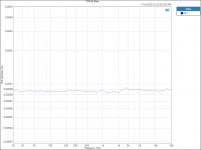
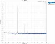
This is the instrument loopback with the same settings. It is not an apple to apples comparison.
The bridge setup has a large external null at the test frequency. I will need to break in and compensate for the null in the THD + N calculations.
The sweep plot of the test bridge does have a completely different shape compared to the loopback curve.
As you are interested in the frequency vs FFT’s plots they will be in the following post.
Thanks DT
Attachments
@Jan,
This is the instrument loopback with the same settings. It is not an apple to apples comparison.
The bridge setup has a large external null at the test frequency. I will need to break in and compensate for the null in the THD + N calculations.
The sweep plot of the test bridge does have a completely different shape compared to the loopback curve.
As you are interested in the frequency vs FFT’s plots they will be in the following post.
Thanks DT
Ahh yes the bridge, slightly complicating things. I was looking at an easy way to do a selftest first. Maybe do a run with the two bridge outputs shorted so that the only thing measured is the CM signal. That should be interesting.
Lookng forward to the actual FFTs!
Jan
@Jan,
Too many plots?
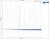
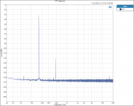
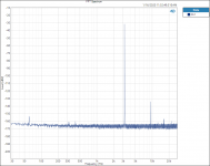
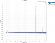
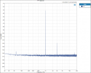
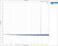
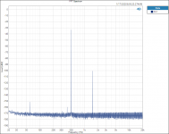
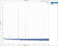
I suppose that this could be automated and put all the plots on one graph with an offset looking like a waterfall. We will see. Using the all thin film NiChrome metal film resistors; 1K Ohms 0.1% 10 ppm, there are 21 plots stepping up from 80hZ to 8KhZ. As the frequency increases from 80 to 8000 the 3rd Harmonic smoothly decreases 20dB’s over that frequency. At that point the 3rdH falls off the high end of the frequency scale.
The file name of the plots includes the test frequency. All the tests were done at 20 Volts input.
80
100
125
160
200
250
315
400
500
630
800
1000
1250
1600
2000
2500
3150
4000
5000
6300
8000
Thanks DT
Too many plots?
I suppose that this could be automated and put all the plots on one graph with an offset looking like a waterfall. We will see. Using the all thin film NiChrome metal film resistors; 1K Ohms 0.1% 10 ppm, there are 21 plots stepping up from 80hZ to 8KhZ. As the frequency increases from 80 to 8000 the 3rd Harmonic smoothly decreases 20dB’s over that frequency. At that point the 3rdH falls off the high end of the frequency scale.
The file name of the plots includes the test frequency. All the tests were done at 20 Volts input.
80
100
125
160
200
250
315
400
500
630
800
1000
1250
1600
2000
2500
3150
4000
5000
6300
8000
Thanks DT
Attachments
-
 630hZ 1M 20avr 20v.PNG42.5 KB · Views: 114
 -
 500hZ 1M 20avr 20v.PNG42.6 KB · Views: 91
 -
 400hZ 1M 20avr 20v.PNG43.7 KB · Views: 89
 -
 315hZ 1M 20avr 20v.PNG43.4 KB · Views: 80
 -
 250hZ 1M 20avr 20v.PNG42.1 KB · Views: 79
 -
 200hZ 1M 20avr 20v.PNG41.1 KB · Views: 290
 -
 160hZ 1M 20avr 20v.PNG41.8 KB · Views: 293
 -
 125hZ 1M 20avr 20v.PNG41.6 KB · Views: 295
 -
 100hZ 1M 20avr 20v.PNG44.4 KB · Views: 309
 -
 80hZ 1M 20avr 20v.PNG44.6 KB · Views: 289
more posts
Attachments
-
 3150hZ 1M 20avr 20v.PNG42.8 KB · Views: 78
 -
 4000hZ 1M 20avr 20v.PNG43.1 KB · Views: 80
 -
 5000hZ 1M 20avr 20v.PNG43.4 KB · Views: 70
 -
 6300hZ 1M 20avr 20v.PNG43 KB · Views: 90
 -
 2500hZ 1M 20avr 20v.PNG43 KB · Views: 84
 -
 2000hZ 1M 20avr 20v.PNG42 KB · Views: 93
 -
 1600hZ 1M 20avr 20v.PNG41.3 KB · Views: 95
 -
 1250hZ 1M 20avr 20v.PNG41.3 KB · Views: 101
 -
 1000hZ 1M 20avr 20v.PNG43.4 KB · Views: 107
 -
 800hZ 1M 20avr 20v.PNG43.2 KB · Views: 103
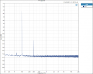
DT, impressive work. I have one Q though - why is the fundamental shown at about -30dB? Is that the attenuation of the bridge?
20V to -28dBV?
20V is +26dBV so if your 3rd shows -130dBV that 3rd is actually -156dB below the fundamental.
To avoid possible confusion is to set the graph to dBr and set the dBr reference for that channel on the AP to +26.
Then again, the input may be 20V, but what is the input across the resistor under test? These are sneaky things.
Jan
Last edited:
@Jan,DT, impressive work. I have one Q though - why is the fundamental shown at about -30dB? Is that the attenuation of the bridge?
20V to -28dBV?
20V is +26dBV so if your 3rd shows -130dBV that 3rd is actually -156dB below the fundamental.
To avoid possible confusion is to set the graph to dBr and set the dBr reference for that channel on the AP to +26.
Then again, the input may be 20V, but what is the input across the resistor under test? These are sneaky things.
Jan
Yes about -30dB is due to the attenuation/null of the bridge.
Yes the input is 20 Volts RMS.
Yes the 3rd is actually -156dB below the fundamental.
The delta across each single resistor under test is 10 Volts and 10 Volts across the reference resistor (4, 1K resistors in series and parallel, the assembly equaling a total of 1K).
Sneaky and tricky to put your head around all at the same time. Then try to calculate the heat inputs and temperature rises and model the distortion and noise.
My thought, measure first then model and calculate.
Thanks DT
Edit: the Vishay 1K 0.01% resistors just arrived at the door.
Edit: about 30 db +26 = about 56dB so 56+ the measured -120dB is a total of -176dB's 3rdH
Last edited:
So then should we not use 10V across the test resistor as reference? 20dB instead of 26dB for 20V?
Jan
Jan
So then should we not use 10V across the test resistor as reference? 20dB instead of 26dB for 20V?
Jan
Yes,
I believe it is even more more sneaky after that.
There are two resistors under test one in the top of the bridge and one in the bottom on the other side of the bridge. The voltage and distortion across each are equal and opposite to each other, effectively doubling the delta measured across the bridge. If both of the resistors were both on the top or bottom of the bridge they would cancel each other leaving nothing to measure.
I am afraid that I still need to close one eye and stand on the other foot to get a handle on this thing.
Still thinking on it.
Thanks DT
You are talking something counterintuitive on my opinion.
Vovk Z,
things may get even more counterintuitive by the fact that heat is not just a practical inconvenience, but a source of distortion too. It is important to keep the thermal energy low, but not by increasing efficiency.
Vovk Z,
things may get even more counterintuitive by the fact that heat is not just a practical inconvenience, but a source of distortion too. It is important to keep the thermal energy low, but not by increasing efficiency.
Battery + supercap + ice cold mineral oil over the circuit board..
@Jan and All,
You were right in your math adding up dB’s.
Meanwhile I am going to keep the test procedures largely the same and do the test bridge accounting after the fact. I do not want to measure the foil resistors with a dBR scale and have different and confusing plots.
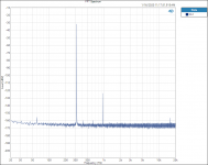
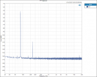
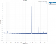
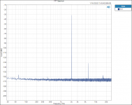
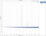
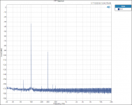
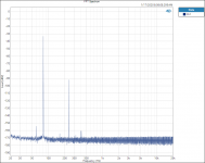
That being said I did do the set of FFT vs frequency plots for the Vishay S102 1Kohm foil resistors, this time with 10 averages rather than 20. The plots went faster and look nearly the same as the 20 average plots. The rest is same same with 20 Volts input to the test bridge.
The surprise to me is how much more distortion the foil resistors produce compared to the thin film / metal film NiChrome resistors (Vishay PTF65 resistors)
Thanks DT
hZ at 20 Volts input to test bridge
80
100
125
160
200
250
315
400
500
630
800
1000
1250
1600
2000
2500
3150
4000
5000
6300
8000
You were right in your math adding up dB’s.
Meanwhile I am going to keep the test procedures largely the same and do the test bridge accounting after the fact. I do not want to measure the foil resistors with a dBR scale and have different and confusing plots.
That being said I did do the set of FFT vs frequency plots for the Vishay S102 1Kohm foil resistors, this time with 10 averages rather than 20. The plots went faster and look nearly the same as the 20 average plots. The rest is same same with 20 Volts input to the test bridge.
The surprise to me is how much more distortion the foil resistors produce compared to the thin film / metal film NiChrome resistors (Vishay PTF65 resistors)
Thanks DT
hZ at 20 Volts input to test bridge
80
100
125
160
200
250
315
400
500
630
800
1000
1250
1600
2000
2500
3150
4000
5000
6300
8000
Attachments
-
 500 hZ foil 1M 10 ave FFT.PNG48.1 KB · Views: 78
 -
 400 hZ foil 1M 10 ave FFT.PNG49.4 KB · Views: 78
 -
 315 hZ foil 1M 10 ave FFT.PNG49.3 KB · Views: 70
 -
 250 hZ foil 1M 10 ave FFT.PNG48.1 KB · Views: 78
 -
 200 hZ foil 1M 10 ave FFT.PNG46.4 KB · Views: 86
 -
 160 hZ foil 1M 10 ave FFT.PNG47.3 KB · Views: 87
 -
 125 hZ foil 1M 10 ave FFT.PNG47.4 KB · Views: 99
 -
 100 hZ foil 1M 20 ave FFT.PNG49.7 KB · Views: 137
 -
 80 hZ foil 1M 20 ave FFT.png49.3 KB · Views: 101
 -
 630 hZ foil 1M 10 ave FFT.PNG47.8 KB · Views: 85
- Home
- Design & Build
- Parts
- What causes resistor distortion?