This layout is just for perfboard purpose, not for pcb manufacturing. I normally use massive copper wire for the high current tracks.Be much more generous with the track output to + speaker. If cannot have whole pours for +V&-V make the link as straight as possible so that a DIY can parallel upon the track, thick cooper wire.
You must add a 10k grounding the + input of NE5534 , as you added a capacitor. The 1k resistor in series with 4.7u is useless.
Are you sure? Thought this was standard inverting opamp circuitry.
1K series resistor together with the 9K feedback resistor makes 10x amplification for the opamp.
Are you sure? Thought this was standard inverting opamp circuitry.
1K series resistor together with the 9K feedback resistor makes 10x amplification for the opamp.
Pin number 2 of the opamp is floating. 10k resistor to ground was suggested...
Correcting. 10k grounding -input ,pin 2.
Ah yes that makes sense.
I have received some LM1875 samples from FauxFrench. Thanks again at this point!
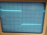
Just swapped one of those into my protoype and tested it a) in inverting configuration with 1k and 2k2, and b) in non-inverting configuration with 1k and 1k plus compensation network.
a) is looking fine now (10kHz ~2Vpp into 8R), only a slight bit of overshoot and no ringing. From this I would conclude that my LM's are crap...
b) is still not really useable. THD and noise should be fine, but the phase margin leaves a lot to be desired.
Attachments

Last edited:

I have received some LM1875 samples from FauxFrench. Thanks again at this point!
Just swapped one of those into my protoype and tested it a) in inverting configuration with 1k and 2k2, and b) in non-inverting configuration with 1k and 1k plus compensation network.
a) is looking fine now (10kHz ~2Vpp into 8R), only a slight bit of overshoot and no ringing. From this I would conclude that my LM's are crap...
b) is still not really useable. THD and noise should be fine, but the phase margin leaves a lot to be desired.
My excuses for having dropped out of the discussion for a week. As the main service agent at my mother-in-law’s house, I had to go and do some important repairs. Now it should do at least for some months.
From your photo’s I guess also you prefer the inverting configuration (a)?
I had less ringing with the non-inverting configuration but asymmetry at higher frequencies.
I simulated your idea of output transistors. Using TIP3055/2955 I get the same results as without . Bridged , it can deliver 150W/8 ohm as the unloaded 1875 can be powered 54v to pour +/-50v to the load.
Does that mean the THD is about the same with and without buffer transistors? 150W/8 Ohm should largely do.
Thanks for the simulation.
Yes, I didn't find any transition distortion from low to high power although the transistors I chose are slow .Does that mean the THD is about the same with and without buffer transistors? 150W/8 Ohm should largely do.
Thanks for the simulation.
I had less ringing with the non-inverting configuration but asymmetry at higher frequencies.
You tested with a much higher level though, IIRC.
Yes, the inverting configuration looks quite useable actually (with that low gain). Unfortunately, anyone building such a circuit would need a square wave generator and an oscilloscope to check whether his LM's are genuine or fake 🙁.
.................................
Unfortunately, anyone building such a circuit would need a square wave generator and an oscilloscope to check whether his LM's are genuine or fake 🙁.
Yes, for those of us who settle with "jellybean parts" in order to avoid excessive shipping costs from reputed suppliers, test is relevant. I may have a useful suggestion to this:
A PC program named "Soundcard Oscilloscope" exists that uses an ordinary 16 bit PC soundcard both as generator (also square-wave) and oscilloscope (44KHz sampling). For the type of misbehavior you observed, this freeware/shareware program should be fully sufficient. I guess we all can get our hands on a simple Windows PC. Evidently it does not test all characteristics of an LM1875.
Last edited:
free download TrueRTA from trueaudio.com
Many thanks for the link. Download of "level 1" (free) done. Can apparently do a lot of things.
Load sharing.
The purpose with more LM1875 in parallel is evidently that they share the load-current quite equally. A mere direct parallel-coupling of the LM1875 outputs will leave harmful cross-currents between the chips and eventual mutual oscillation. Each LM1875 chip needs a certain operational isolation from the other chips such that they have full control with their own output. This is achieved through impedance in their mutual connection.
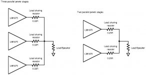
My initial idea was to use traditional resistive load balancing the way it has been used for decades when balancing currents in parallel power transistors, for audio power amplifiers and linear power supplies among other. The principle is shown in the sketch appended.
The value of the load balancing resistors is a compromise between power loss in the resistors, isolation impedance between the individual LM1875 chips and static damping factor seen from the speaker. With maximum current from an LM1875 (2.1Arms), the power loss in 0.5 Ohm would be 2.2W, in 0.33 Ohm 1.5 W and in 0.25Ohm 1.1W.
For isolation from other LM1875 chips, more resistance is better but with a limit where further isolation brings no significant advantage. Imbalance in load current from each LM1875 is reduced when the value of the balancing resistors is increased but power losses will put a limit in practice.
In order to minimize cross-currents and imbalance in load sharing, voltage offset and differences in amplification (gain) need to be kept low. A static output difference, caused by output offset originating from input offset and the amplifier gain, will inherently cause cross-currents. The input offset of an LM1875 chip may be as high as +/-15mV though stated to be typically +/-1mV. 15mV times the gain of an LM1875 power stage would be important with high gain values. As all parallel LM1875 operate from the same input signal, the corresponding output signals must be almost equal in amplitude and phase for minimum imbalance and little risk of significant cross-currents.
The gain needed in an LM1875 power stage I expect to be in the order 3-4 times for use in a composite amplifier. I will explain why in a later posting. I recently tested LM1875 in an inverting configuration with a gain a bit above 2. It was indeed stable though the datasheet states that the gain needs to be above 10. Kokoriantz and palstanturhin already knew it was possible and very recent tests by Preamp show the same. Using a typical input offset of 1mV and multiplying that with a gain of 4 leaves 4mV at the output. Worst case, two LM1875 may have opposite signs of the offset voltages such that the differences at the outputs may be 8mV. The 8mV have to be compensated by the (isolating) load balancing resistors. Between two LM1875 power stage outputs there will be two load balancing resistors connected in series. With load balancing resistors of 0.5 Ohm, the series connection is 1 Ohm and the 8mV offset at the outputs translates into 8mA current. With load balancing resistors of 0.33 Ohm, the series connection is 0.66 Ohm and the 8mV offset at the outputs translates into 12mA current. With 0.25 Ohm load balancing resistors, the current will be 16mA. For LM1875 output stages even a current of 16mA is no problem.
The gain of an LM1875 depends on the feedback resistor between the output and the inverting input, and the further resistor going to the inverting input. While the precision of the absolute gain is of less importance, the relative gain match between parallel LM1875 power stages is important for load balance. Both of the two gain determining resistors may be matched against the same resistors used in parallel LM1875 power stages. While standard metal film resistors are supplied with 1% tolerance, they can be preselected to be within 0.1% of other corresponding resistors using a decent quality digital multimeter. Assuming that both types of resistors are matched within 0.1%, the gains should be matched within 0.2%. The largest deviation in output voltages of parallel LM1875 power stages is at maximum output voltage. Maximum output voltage is about 20V with +/-25V supply voltage. 0.2% of 20V is 40mV. 40mV with 0.5 Ohm load balancing resistors means a load imbalance in the order of 40mV/(0.5 Ohm+0.5 Ohm)=40mA. With 0.33 Ohm load balancing resistors, the imbalance current becomes 61mA and with 0.25 Ohm 80mA. The order of such imbalance currents is no problem for LM1875 supplying close to 3A.
The static damping factor is the size of the load (speaker) impedance compared to the static output impedance of the combined set of parallel LM1875 power stages, when loop correction is not taken into account. The damping factor helps keeping a speaker under control when the speaker, due to inertia, generates voltages on its own. Three 0.5 Ohm load balancing resistors leave a static damping factor of 48 with an 8 Ohm speaker. Two 0.5 Ohm load balancing resistors leave a static damping factor of 32 with an 8 Ohm speaker. Three 0.33 Ohm balancing resistors leave a static damping factor of 73 with an 8 Ohm speaker. Two 0.33 Ohm balancing resistors leave a static damping factor of 48 with an 8 Ohm speaker. Three 0.25 Ohm balancing resistors leave a static damping factor of 96 with an 8 Ohm speaker. Two 0.25 Ohm balancing resistors leave a static damping factor of 64 with an 8 Ohm speaker.
For 4 Ohm speakers, the values will be half of those with 8 Ohm speakers. The dynamic damping factor will be significantly better when the regulation loop counter-acts voltages generated by the speaker.
Even the static damping factor values are decent. My suggestion is to use 0.33 Ohm load balancing resistors when three parallel LM1875 power stages are used. When only two parallel power stages are used, I suggest to use 0.25 Ohm load balancing resistors.
Due to the moderate gain (3 to 4 times) in each LM1875 power stage, it should be possible to avoid individual trimming of offset and gain as long as the gain determining resistors are preselected for equal values.
What-do-you-think?
The purpose with more LM1875 in parallel is evidently that they share the load-current quite equally. A mere direct parallel-coupling of the LM1875 outputs will leave harmful cross-currents between the chips and eventual mutual oscillation. Each LM1875 chip needs a certain operational isolation from the other chips such that they have full control with their own output. This is achieved through impedance in their mutual connection.
My initial idea was to use traditional resistive load balancing the way it has been used for decades when balancing currents in parallel power transistors, for audio power amplifiers and linear power supplies among other. The principle is shown in the sketch appended.
The value of the load balancing resistors is a compromise between power loss in the resistors, isolation impedance between the individual LM1875 chips and static damping factor seen from the speaker. With maximum current from an LM1875 (2.1Arms), the power loss in 0.5 Ohm would be 2.2W, in 0.33 Ohm 1.5 W and in 0.25Ohm 1.1W.
For isolation from other LM1875 chips, more resistance is better but with a limit where further isolation brings no significant advantage. Imbalance in load current from each LM1875 is reduced when the value of the balancing resistors is increased but power losses will put a limit in practice.
In order to minimize cross-currents and imbalance in load sharing, voltage offset and differences in amplification (gain) need to be kept low. A static output difference, caused by output offset originating from input offset and the amplifier gain, will inherently cause cross-currents. The input offset of an LM1875 chip may be as high as +/-15mV though stated to be typically +/-1mV. 15mV times the gain of an LM1875 power stage would be important with high gain values. As all parallel LM1875 operate from the same input signal, the corresponding output signals must be almost equal in amplitude and phase for minimum imbalance and little risk of significant cross-currents.
The gain needed in an LM1875 power stage I expect to be in the order 3-4 times for use in a composite amplifier. I will explain why in a later posting. I recently tested LM1875 in an inverting configuration with a gain a bit above 2. It was indeed stable though the datasheet states that the gain needs to be above 10. Kokoriantz and palstanturhin already knew it was possible and very recent tests by Preamp show the same. Using a typical input offset of 1mV and multiplying that with a gain of 4 leaves 4mV at the output. Worst case, two LM1875 may have opposite signs of the offset voltages such that the differences at the outputs may be 8mV. The 8mV have to be compensated by the (isolating) load balancing resistors. Between two LM1875 power stage outputs there will be two load balancing resistors connected in series. With load balancing resistors of 0.5 Ohm, the series connection is 1 Ohm and the 8mV offset at the outputs translates into 8mA current. With load balancing resistors of 0.33 Ohm, the series connection is 0.66 Ohm and the 8mV offset at the outputs translates into 12mA current. With 0.25 Ohm load balancing resistors, the current will be 16mA. For LM1875 output stages even a current of 16mA is no problem.
The gain of an LM1875 depends on the feedback resistor between the output and the inverting input, and the further resistor going to the inverting input. While the precision of the absolute gain is of less importance, the relative gain match between parallel LM1875 power stages is important for load balance. Both of the two gain determining resistors may be matched against the same resistors used in parallel LM1875 power stages. While standard metal film resistors are supplied with 1% tolerance, they can be preselected to be within 0.1% of other corresponding resistors using a decent quality digital multimeter. Assuming that both types of resistors are matched within 0.1%, the gains should be matched within 0.2%. The largest deviation in output voltages of parallel LM1875 power stages is at maximum output voltage. Maximum output voltage is about 20V with +/-25V supply voltage. 0.2% of 20V is 40mV. 40mV with 0.5 Ohm load balancing resistors means a load imbalance in the order of 40mV/(0.5 Ohm+0.5 Ohm)=40mA. With 0.33 Ohm load balancing resistors, the imbalance current becomes 61mA and with 0.25 Ohm 80mA. The order of such imbalance currents is no problem for LM1875 supplying close to 3A.
The static damping factor is the size of the load (speaker) impedance compared to the static output impedance of the combined set of parallel LM1875 power stages, when loop correction is not taken into account. The damping factor helps keeping a speaker under control when the speaker, due to inertia, generates voltages on its own. Three 0.5 Ohm load balancing resistors leave a static damping factor of 48 with an 8 Ohm speaker. Two 0.5 Ohm load balancing resistors leave a static damping factor of 32 with an 8 Ohm speaker. Three 0.33 Ohm balancing resistors leave a static damping factor of 73 with an 8 Ohm speaker. Two 0.33 Ohm balancing resistors leave a static damping factor of 48 with an 8 Ohm speaker. Three 0.25 Ohm balancing resistors leave a static damping factor of 96 with an 8 Ohm speaker. Two 0.25 Ohm balancing resistors leave a static damping factor of 64 with an 8 Ohm speaker.
For 4 Ohm speakers, the values will be half of those with 8 Ohm speakers. The dynamic damping factor will be significantly better when the regulation loop counter-acts voltages generated by the speaker.
Even the static damping factor values are decent. My suggestion is to use 0.33 Ohm load balancing resistors when three parallel LM1875 power stages are used. When only two parallel power stages are used, I suggest to use 0.25 Ohm load balancing resistors.
Due to the moderate gain (3 to 4 times) in each LM1875 power stage, it should be possible to avoid individual trimming of offset and gain as long as the gain determining resistors are preselected for equal values.
What-do-you-think?
Attachments
Last edited:
The gain setting resistors have to be matched to something like 0.1% or better. Simply using off-the-shelf 1% metal films won't cut it and the cross-currents will be too huge. The load sharing resistors seem to be just fine with a simulated 5% though, so no need to match 0.33 Ohm 😉.
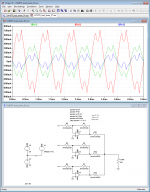
Run the attached monte carlo simulation for yourselves (with LTspice) and observe the currents through the load sharing resistors and the power dissipation of each opamp.
For a simple illustration I went with a gain of 4 and 5Vp input with 25V rails, for 20Vp output into a light 100R load. Load current will be 200mAp for 4Wp output power. Worst case sim shows about 23mAp/40mAp/136mAp through the three load sharing resistors, and that's with 0.1% gain resistors already! Of course the currents start to equalize somewhat better when the output current rises, but that doesn't look nice at all...
One caveat for this particular simulation: when you lower the load resistor to something like 8R, you'll notice that the output will clip. This is due to the simple opamp model being current limited, independent of what you enter for its ilimit parameter.
EDIT: Added another sim result for 1% gain resistors. We now get 700mA peak from one opamp, for only 200mA total output current. That's to be avoided...
EDIT2: Go to the menu "Plot Settings" > "Select Steps" to view a single run only and thus remove some clutter from the waveform viewer. #6 is worst-case, while #8 is about as good as it gets.
Attachments

Last edited:
Hi FF
Impressive !.. i have to recheck this at my "normal" paralleling LM1875. the DC offset is always about -1,8mV or 2,2mV so offset is not a huge problem - but with gain setting i should do some investigation - especially with higher power output.
does it make sense to keep every composite amp with its gain( as accurate as possible) and add the corrected load sharing resistor for each composite amp?
chris
Hi Chris,
It makes sense to preselect (match) the gain setting resistors such that trimming of them becomes unnecessary. The low resistance (power) load sharing resistors should not be corrected as they are difficult to adjust and trimming would only influence load sharing moderately. Keep the load sharing resistors standard 5% as concluded by Preamp.
It makes sense to preselect (match) the gain setting resistors such that trimming of them becomes unnecessary. The low resistance (power) load sharing resistors should not be corrected as they are difficult to adjust and trimming would only influence load sharing moderately. Keep the load sharing resistors standard 5% as concluded by Preamp.
.......................
For a simple illustration I went with a gain of 4 and 5Vp input with 25V rails, for 20Vp output into a light 100R load. Load current will be 200mAp for 4Wp output power. Worst case sim shows about 23mAp/40mAp/136mAp through the three load sharing resistors, and that's with 0.1% gain resistors already! Of course the currents start to equalize somewhat better when the output current rises, but that doesn't look nice at all.....................
Hi Lasse,
My impression is that the observed load imbalance is due to the very low loading (100R). With only 200mA load current, currents in the low impedance load balancing resistors caused by differences in output voltages are relative large compared to the moderate load current. If you change the 100 Ohm into 8 Ohm, the relative difference in LM1875 currents become much less. One LM1875 may supply good 100mA more than the two other but when they share 2.5A as 780mA, 795mA and 925mA it looks less frightening. In BTL configuration (still 8 Ohm load), the load current will be 5A and the split 1610mA, 1625mA and 1755mA which looks even less scary. Is your fear that the relatively large imbalance at momentary low load current is going to cause a kind of cross-over distortion?
NB: If your OP-AMP simulation model does not allow for higher currents, keep the 100 Ohm loading but increase the load sharing resistors with 12 times as well (use 4 Ohm) and run your simulation again.
Last edited:
- Home
- Amplifiers
- Chip Amps
- LM1875 in parallel configuration and used in a composite amplifier.