so wire should go.... iec-fuse-switch-pt-iec ?
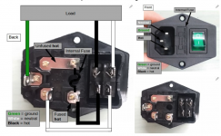
The illustration below shows the connection sequence for the incoming line power. The line (or hot) side has voltage potential relative to ground so you want to fuse it as soon as it enters the amp to minimize chances for shorting the unfused portion of the line voltage supply. I stole the image from this website Wire Up a Fused AC Male Power Socket: 4 Steps (with Pictures) but I can't vouch for any of their instructions.
The IEC socket in the image also has a built in fuse and switch, but the switch could be located anywhere.
Attachments
Bringing the windings parallel just makes the xformer capable of delivering more current, the regulators don't care.
Rest is correct 🙂
Jesper.
From my (limited) experience the transformer voltage is rated with a full load and when under loaded the voltage will be higher.
My thinking was that this would lead to a higher voltage into the reg which would have to be dissipated.
The illustration provided by csample is helpful, but I humbly suggest an IEC inlet like this one for three reasons:
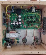
The photos illustrate two separate installations using the same make and model linked above. The one on the left shows one of a pair of monoblocks I built some two years back. The right photo is of the TSEII I completed this past summer prior to bonding the ground lug to the chassis (this was completed shortly after this was taken). The ceramic strip makes the installation look more complicated than it actually is:

- Since - like your power cord itself - there are only three lugs (Hot, Neutral and Ground), installation is practically a "no-brainer". All you have to do is connect three wires (see below) and you're done. Oh, and you can place the switch anywhere you want, within reason of course.
- Both the hot and neutral lugs are fused. Just be sure to order a bunch of 5 x 20 mm fuses of the correct rating. I usually order 10 - just in case. They're cheap.
- There's a built-in filter to reduce any spurious power line noise.
The photos illustrate two separate installations using the same make and model linked above. The one on the left shows one of a pair of monoblocks I built some two years back. The right photo is of the TSEII I completed this past summer prior to bonding the ground lug to the chassis (this was completed shortly after this was taken). The ceramic strip makes the installation look more complicated than it actually is:
- HOT => Inrush Current Limiter (the black thing) => switch => Xformer primary 1
- NEUTRAL => Xformer primary 2
- GND => Chassis
Attachments


super helpful info, thanks!!The illustration provided by csample is helpful, but I humbly suggest an IEC inlet like this one for three reasons:
At around $16 US a pop they're certainly not what I'd call inexpensive, but I consider them to be an absolute bargain all things considered. The only janky thing is having to cut out an appropriate hole in the chassis, but if you're considering building a tube amp that's the least of your concerns.
- Since - like your power cord itself - there are only three lugs (Hot, Neutral and Ground), installation is practically a "no-brainer". All you have to do is connect three wires (see below) and you're done. Oh, and you can place the switch anywhere you want, within reason of course.
- Both the hot and neutral lugs are fused. Just be sure to order a bunch of 5 x 20 mm fuses of the correct rating. I usually order 10 - just in case. They're cheap.
- There's a built-in filter to reduce any spurious power line noise.
The photos illustrate two separate installations using the same make and model linked above. The one on the left shows one of a pair of monoblocks I built some two years back. The right photo is of the TSEII I completed this past summer prior to bonding the ground lug to the chassis (this was completed shortly after this was taken). The ceramic strip makes the installation look more complicated than it actually is:
I hope this helps, and that I'm not flogging a dead horse. These things are easy to overthink, and I have to keep telling myself, "simplicity is key".
- HOT => Inrush Current Limiter (the black thing) => switch => Xformer primary 1
- NEUTRAL => Xformer primary 2
- GND => Chassis
Some more TSE-II wiring questions
Like Bryce, I am also in the wiring phase on my TSE-II and had a question on the wiring diagram shared in post 598.
I don't understand the reason to bring the negative speaker output terminals to the star ground. I see that Tubelab does this on the Simple SE, but I don't see it in TSE-II build photos like Mr_Zenith's. Should this be done for the TSE-II?
Also, would it be beneficial to switch both the incoming line and neutral leads? I see the Simple SE schematic shows this (however SSE wiring diagram does not), and so does the power supply schematic for the Nelson Pass Burning Amp series. If both George and Nelson do it, there must be a good reason to do so. Can anyone explain?
Lastly, does the TSE-II need the inputs brought to the star ground like the Simple SE? (diagram below).
Thanks
*** The diagram is from the Tubelab Simple SE Assembly Manual for Reference***
Attachments
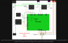
The cold side of each speaker should be connected to ground in case a short develops in the OPT. Such a short is rare but can put B+ on the speaker wiring.
Switching the neutral side of the line voltage is required in some countries. I personally don't switch the neutral, but I have a big box full of SPST appliance power switches.
The input connections to the board are routed to the negative side of the power supply caps on the board itself. This is the true star ground point. No other ground connections are needed or wanted.
Am i right in thinking that the 4 pin tube socket numbering is correct on this board? When looking at the instructions for the original it says it wasn't.
Also -- my 4 pin sockets have no numbers. Can the 4 pins tubes be inserted in any orientation? In that case I just need to make my own mark, and it doesn't matter how the socket is installed, I think?
Also -- my 4 pin sockets have no numbers. Can the 4 pins tubes be inserted in any orientation? In that case I just need to make my own mark, and it doesn't matter how the socket is installed, I think?
The 4pin socket has 2 holes larger than the other 2.
The 2 large pins (1 and 4) are the filament. They should both be on the right side (when facing the board from the front)
The 2 large pins (1 and 4) are the filament. They should both be on the right side (when facing the board from the front)
I don't remember off the top of my head whether the pin numbering is correct on the new board, but I think it is. Regardless, itsikhefez is correct. The filament pins can also be distinguished by the mongo traces connecting them. This is so they can carry the 5A required to light a pair of 2A3s.
In addition to having the correct orientation, you also have to remember to mount the sockets on the printed (upper) side of the board. Otherwise you'll swap the plate and grid leads (not good). The grids just won't dissipate 15 W - well, not for long anyway. Don't ask me how I know, I just know... 😀
And picapiedra, I haven't forgotten about you. I'm just crazy-busy at the moment...
Am i right in thinking that the 4 pin tube socket numbering is correct on this board? When looking at the instructions for the original it says it wasn't.
Yes, the old board was numbered to match the (incorrectly made) sockets I had at the time the very first hand made SE-45 board was made….before the TSE, or Tubelab itself was even a thing. The mistake went unnoticed for several years until the TSE boards were being produced for a year or so. It would cost me setup and artwork fees to get them fixed, so they stayed wrong for what turned out to be 14 years.
The new board was a fresh PCB design, so a laundry list of small changes were made at that time. The pin numbers on the new board are correct.
All of the 4 pin tubes use two different pin diameters. The fatter two pins are the filament (pins 1 and 4). The skinny two pins are the grid and plate. Trust me if you try hard enough the fat pins will fit into the skinny holes. In some sockets, you don't have to try all that hard. In my case the filament in the 45's survived the plate voltage. The grid stoppers and one mosfet did not.
Happy new year!
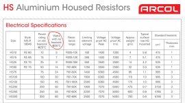
I'am in for the D6 diode... I have outboard R36 power resistor and going with the 300b tubes, so i have to use the 150v zener, making the heat goes more into the R36 as stated below right?
Jesper.
I'am in for the D6 diode... I have outboard R36 power resistor and going with the 300b tubes, so i have to use the 150v zener, making the heat goes more into the R36 as stated below right?
R36 is a resistor, it has bypass caps on both ends, you can mount it on wires in the next zip code and it won't matter. If you are going to mount R36 off board, use the 150 volt zener for D6 to put more heat into R36, and less into the mosfets. Make R36 a 10 watt part. That removes the biggest heat source from the board. Use one of those gold anodized chassis mount resistors and you put the heat into the chassis, not the board.
Jesper.
Happy new year!
I'am in for the D6 diode... I have outboard R36 power resistor and going with the 300b tubes, so i have to use the 150v zener, making the heat goes more into the R36 as stated below right?
"R36 is a resistor, it has bypass caps on both ends, you can mount it on wires in the next zip code and it won't matter. If you are going to mount R36 off board, use the 150 volt zener for D6 to put more heat into R36, and less into the mosfets. Make R36 a 10 watt part. That removes the biggest heat source from the board. Use one of those gold anodized chassis mount resistors and you put the heat into the chassis, not the board. "
Jesper.
Hi Jesper, your quote was posted by George, so I would trust it. I am going this route on my 300B TSE-II. You probably already know this, but I was surprised to learn that the rated power values for chassis mounted resistors applies only when mounted to a heatsink. They are derated when mounted without adequate ability to transfer heat to their mounting surface. The screen shot below is from the Ohmite/Arcol catalog for their aluminum housed chassis mounted resistors.
Happy New Year!
Chas
Attachments
Happy new year too 🙂
Thanks, just needed to be sure that i had my notes right. About the heatsink i was aware, the same aplies to most other parts like mosfets, ldo's etc...
I'am also in for the 300b Build, waiting for my parts to arrive which will happen somewhere mid/late january according to Toroidy 🙂
Good 1. Januar
Jesper.
Hi Jesper, your quote was posted by George, so I would trust it. I am going this route on my 300B TSE-II. You probably already know this, but I was surprised to learn that the rated power values for chassis mounted resistors applies only when mounted to a heatsink. They are derated when mounted without adequate ability to transfer heat to their mounting surface. The screen shot below is from the Ohmite/Arcol catalog for their aluminum housed chassis mounted resistors.
Thanks, just needed to be sure that i had my notes right. About the heatsink i was aware, the same aplies to most other parts like mosfets, ldo's etc...
I'am also in for the 300b Build, waiting for my parts to arrive which will happen somewhere mid/late january according to Toroidy 🙂
Good 1. Januar
Jesper.
For those building their boards with the components on the bottom, sealed in a chassis, have you been upgrading the heat sink for IC3? In the instructions for the original Tubelab SE I know the Sharp part needs extra attention, is that the case with the new one as well?
And if so, is it only IC3 I need to worry about, heat wise? If needed, I was going to take a heat sink from an old PC board and attach to the IC3 heat sink.
And if so, is it only IC3 I need to worry about, heat wise? If needed, I was going to take a heat sink from an old PC board and attach to the IC3 heat sink.
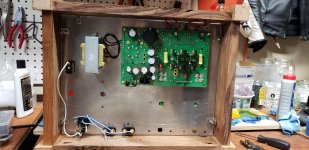
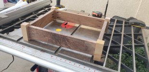
Making progress
I built my enclosure over the past few days and started final assembly. Just waiting on transformers and it will be done. It has been fun mixing multiple hobbies into a single project. Hoping the checkout process goes smoothly.
I built my enclosure over the past few days and started final assembly. Just waiting on transformers and it will be done. It has been fun mixing multiple hobbies into a single project. Hoping the checkout process goes smoothly.
Attachments

Does anyone here know how to get in touch with George?
I've emailed and PMed with questions about the SSE - just need confirmation that boards are still available and it is still a viable project (all parts are still available) before I send my money for a SSE board. Maybe someone else here knows the answer?
I've emailed and PMed with questions about the SSE - just need confirmation that boards are still available and it is still a viable project (all parts are still available) before I send my money for a SSE board. Maybe someone else here knows the answer?
Order the boards on his website, pay via PayPal. Ordering | Tubelab
I have built two of his amps and recommend that you start with the SSE because it is thoroughly documented on the Tubelab website. My Tubelab SSE amp has two 6L6GC output tubes, a GE 12AT7 tube and a Mullard 5AR4. Sounds really nice.
However, I've recently been extremely impressed with the TSE-II board running two number 45 output tubes.
Plan is to build another TSE-II amp with 300B output tubes so I can listen with my beer muffs on. (I get a little hard of hearing, similar to wearing ear muffs, when I've been binge drinking. That means four or more beers in a row).
George has a lot of other things going on, has always answered my questions about Tubelab boards when I've posted questions. You also need to read through the website and DIY Audio to get the nitty-gritty details. That's why it's called DIY.
Make sure to look at all the photos of the Tubelab amps to stay properly motivated and build your own amp.
- Home
- More Vendors...
- Tubelab
- After a 14 year run, the TSE must DIE!