Perhaps some info of interest to AK4499 dac builders: Just tried hooking up an external AK4137 board to the AK4499 eval board. When set to DSD256 it sounds better to me than some (or many) of HQ Player conversion options, but not better than the very best and most computationally demanding options HQ Player can do.
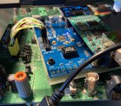
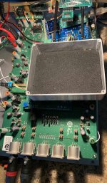
Some pics below for your viewing pleasure. An Amanero USB board is used with the AK4137 because the two are designed to easily plug together and ASIO drivers are available. The I2S wires were left longer than might have been best, but I wasn't sure how the board was going to fit in the space available. A bare perfboard was attached to the bottom of the AK4137 board to provide some safety insulation.
Also in the pics the bottom half of a Hammond box can be seen sitting on top of some of the eval board. It seems to work best were it is shown sitting to help provide some shielding between the more sensitive dac circuitry, the AK4137 board, and the I2S interconnection wiring. I just moved it around to find the cleanest sounding spot 🙂
Attachments

Too bad you can't demonstrate it with measurements or objective listening test.it sounds better to me than some (or many) of HQ Player conversion options, but not better than the very best and most computationally demanding options HQ Player can do.

Fortunately, this thread is for a DAC project people can experiment with however they want. No doubt some will post measurements as anyone is free to do. Please be patient or if can't wait then maybe try getting busy building and measuring your own.
Last edited:
Will you be getting busy with any objective listening test to verify your DAC perceptions?Please be patient or if can't wait then maybe try getting busy building and measuring your own.
Mark, trying to bring this thread back OT yet again — thanks for all the help in that regard. Wondering why you’re using the external 4137 over the one on the eval board, I imagine the implementation can’t be that different. Is it just to interface with the Amanero USB module?
Adam,
The eval board AK4137 might be preferable in some ways, however the eval board does not provide an option to route external I2S input through the AK4137. It only allows optional use of AK4137 in conjunction with the AK4118 SPDIF receiver.
Possibly eval board PCB traces between AK4118 and AK4137 could be hacked to allow insertion of external I2S. The setup in the pics was easy for a quick tryout.
Also, some suspicion the AK4137 board in the pics could sound a little better than I have it now. Used its clocks, and also its default configuration which takes the MCLK signal for AK4499 from the AK4137 chip rather than directly from the clock modules. Pretty sure the clock modules direct should be lower jitter. Don't know if I would need to buffer them. Also possible to try different clocks, improve their power supply, etc. Don't know which mods might help most. Always ways to spend time experimenting with DACs 🙂
Last edited:
Hi Adam,
have been following this thread with keen interest as I am hoping to learn something from it, and hopefully the project continue to develop well.
I have a question though, I am not too familiar with all the DAC stuff in the DIY world, but would like to ask if you are going/have to program what ever controller now will be implemented and will that also become open source, thanks.
Regards Michael
Michael — Open source is the name of the game here! Planning on using either an AtMega / Arduino compat. chip, or an ARM core — either way, the source code will be documented and put up on github.
i am thinking of using this https://hr.mouser.com/datasheet/2/609/hmc194a-1503833.pdf to switch between clock source near ak4137 and ufl connector clock input, in place of jumpers, so it could be changed by electronics/software/button etc...
what do you say is it fesible?
what do you say is it fesible?
Its a microwave IC, designed for 50 ohm impedance signals only. Most logic chips cannot drive as low as 50 ohms.
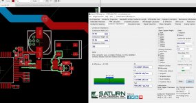
I was thinking more along the lines of something like the ADCLK950 from analog, with 75fs of additive jitter, I'll need to dig into the datasheet a bit more as it looks like it only takes differential clocks, so I'll need to either find a solution or source a different part, but because jitter adds in RSS form, I don't think the jitter from this chip will be a problem. Tonitonitoni -- Is via stitching built into eagle?
Last edited:
no it is not, i am not sure why this isnt automated as it is very time consuming and tedious, it probably could be programed easy to suit different needs.
since this is neither cheap nor easy device, why not go with some solution that doesnt require fiddling around pcb after device is assembled and closed. please someone check is 7SB3257 applicable here, or recomend part that could be used, also it would realy be nice to switch clock source via simple button press.
or make 2 different pcbs one with clock routed to connector and no xtal on board, and one with clock and no connector. please advise.
or make 2 different pcbs one with clock routed to connector and no xtal on board, and one with clock and no connector. please advise.
- Home
- Source & Line
- Digital Line Level
- AK4499 DAC Design