I am putting together a 4 deck version, and have 8 tent 3.3v regulators for them.
The tent shunt reg’s shall have between 7- and 10 v dc in. I have a salas sslv 1.3 feeding the main board. So instead of a dropping R on each tentboard: may I lower the VDC in on the mainboard ?
And if OK : how much ?
Best wishes for the rest of Christmas
The tent shunt reg’s shall have between 7- and 10 v dc in. I have a salas sslv 1.3 feeding the main board. So instead of a dropping R on each tentboard: may I lower the VDC in on the mainboard ?
And if OK : how much ?
Best wishes for the rest of Christmas
I am putting together a 4 deck version, and have 8 tent 3.3v regulators for them.
The tent shunt reg’s shall have between 7- and 10 v dc in. I have a salas sslv 1.3 feeding the main board. So instead of a dropping R on each tentboard: may I lower the VDC in on the mainboard ?
And if OK : how much ?
Best wishes for the rest of Christmas
The analog supply for the dac chips is 8 volt . The embedded 8v tent shunt needs 10 Volt, which is pre regulated on the dac boards with a 7810. This one needs 1,5 volt in to out, so without the serial resistor, you still need minimum 11,5 volt. That is not what you are looking for, so an option would be to not install the 7810, leave the resistor at the input away and feed with 10 volt the main board ( and hence the dac boards )
Doing so, you will lose any form of safety-net for too high voltages or other power supply voltages going wrong or rogue. So the risk to make sure nothing goes wrong is fully up to you...
So a dropping R in on each tent shunt reg then?
If you mean the 3,3 Volt ones, yes that would be the easiest solution. The digital side of the dac chip draws ( from memory ), depending on FS frequency, 25 to 50 mA, so probably a 1 Watt 100ohm will do fine...
Hello,If you mean the 3,3 Volt ones, yes that would be the easiest solution. The digital side of the dac chip draws ( from memory ), depending on FS frequency, 25 to 50 mA, so probably a 1 Watt 100ohm will do fine...
I think ALL the information you need about how to make the Tent shunts perfectly is on their website.
As Doede mentioned before he did install a preregulation on his circuit to be sure the input voltage does not get above 10 volts. I remember some people claim it sounds better without the 7810 ( if you are willing to take the risk of overheating the shunt if the input is higher because of whatever reason).
There could be regulators with better sonics than the 7810. It seems logic that most of advantages from the new style supply are coming from the shunt and from the fact the shunt is close to the actual load.
Removing all the 7810 from the circuit once the complete 4 level dddac is time consuming.
I might do it in a few years...
Greetings, Eduard
I posted earlier about fitting the 3045 5v and 3.3v on the main board and finding they sounded really good straight away. I also thought that with some time allowed for burning in, they would sound even better.
I was wrong unfortunately.
After a few days had passed, it just did not sound right at all. It seemed to have lost the 3D effect and although very clear sounding, it had lost it's depth and spread.
So I put the LF33 and LF50 back in place and played the Dac on repeat for a few days.
I checked it out yesterday and it is now back to its 3D sound with the height and spread that made this such a wonderful Dac to listen to.
I tried Superregs about a year ago with the same result, then a Micral 1a regulator.
But in the end I always end up going back to the LF regulators as per the original parts supplied.
They may have more noise than the uprated regs, but there is something about the LF regs that just work so well together, so I have learned my lesson now to leave things the way they were designed in the first place.
Power supplies can be changed about quite a bit with chokes instead of resistors or uprating to TIP142 transistors, Mundorf power supply caps etc, but from now on I will leave the main board as is except the change to Poly caps and Vishay RVI caps on the input.
I will be trying to run 16 Tent Dac boards later in the year without any component changes to see if the main board will be able to drive the boards, as I am running 16 pre Tent boards at the moment successfully.
So I would recommend running the original boards and components first for a couple of months, to give you an idea of how well the original design sounds, then make the modifications afterwards.
Try it for a month or so and check you still have that wonderful 3D sound. If not, just put it back to original spec and enjoy 🙂
I posted earlier about fitting the 3045 5v and 3.3v on the main board and finding they sounded really good straight away. I also thought that with some time allowed for burning in, they would sound even better.
I was wrong unfortunately.
After a few days had passed, it just did not sound right at all. It seemed to have lost the 3D effect and although very clear sounding, it had lost it's depth and spread.
So I put the LF33 and LF50 back in place and played the Dac on repeat for a few days.
I checked it out yesterday and it is now back to its 3D sound with the height and spread that made this such a wonderful Dac to listen to.
Interesting! Is this something that changed in the 3045 regs during "break in", or was this more a perceivment thing ("brain break in")? Something similar happened to me recently when someone tried to sell a "cable upgrade" for my headphones. I went back and forth between the two cables, and I was convinced the "upgrade" does sound much better. Then I did a blind test to see if I could tell the two cables apart (with the help of a friend). My replies were as good as a random guess machine... go figure.
Thanks for letting us know that the regulator upgrade might not be necessary after all 😉
I am looking forward to your work on the 16 deck DDDAC. Didn't you run into problems with 16 Tent decks in the past?
Hello,
It could well be that all these spectacular specs comes at a cost. Remember the days when some big well known brands were producing power amps with very high damping factors. I heard a few but it was not my cup of tea.
Those days there were devices like the Nad3020, rappaport, sonotron, the first electrocompaniet that were doing things very good with having the specs.
I guess that with regulators if you are aiming at specs beyond imagination you end up on the wrong side.
Greetings, Eduard
Interesting! Is this something that changed in the 3045 regs during "break in", or was this more a perceivment thing ("brain break in")? Something similar happened to me recently when someone tried to sell a "cable upgrade" for my headphones. I went back and forth between the two cables, and I was convinced the "upgrade" does sound much better. Then I did a blind test to see if I could tell the two cables apart (with the help of a friend). My replies were as good as a random guess machine... go figure.
Thanks for letting us know that the regulator upgrade might not be necessary after all 😉
I am looking forward to your work on the 16 deck DDDAC. Didn't you run into problems with 16 Tent decks in the past?
It was definitely a burn in change, because I was so surprised at how well the 3045`s worked from the moment I switched it on, it sounded just like the burnt in LF regs. That is why I leave any mods I do alone for a long time to make sure I am not being fooled by any expectation bias.
I leave the Dac powered up 24/7 so it is ready to go instantly but the lack of depth and 3D space just went away and it was not enjoyable to listen to any more. I had the same experience with the Superregs and a set of Micral regs as well. The LF regs are staying for good this time.
I did try a 16 stack tent reg setup but could not get rid of the distorted sound that was the same as trying the early Red main board with 8 pre Tent Dac boards. It was when Doede brought out the SPDIF main board, the distortion went away and I got the 16 Dac boards running.
I could not get rid of the distortion when running 16 Tent boards, but it could have been my fault for not using the original Muse capacitors. I ordered some Polymer capacitors instead so that may have caused the problem somehow with the very low ESR.
I checked the I2s waveforms on both versions at the top of the stack and they looked identical.
there was quite a lot of noise on the top part of the square wave signal on both versions, but the Tent days just would not stop distorting no matter what I tried.
I will have a word with Doede soon to see if I can have an extra buffer to power each of the I2s lines. I will be drawing up the circuit in KiCad for an evaluation later in the year.
That ‘s right Simon. But don’t forget 5v and gnd from waveio i2s to J1 on fifo, pin 2 and 6.
You also need to connect 5v and gnd from dddac i2s to pin 2 (5v) and pin 6 (gnd) on J2. If not, waveio’s i2s chip will not work, and no sound.
Good luck. 🙂
Would you mind confirming I have this all connected correctly in the attached diagram? Thanks 🙂
Attachments
If you mean the 3,3 Volt ones, yes that would be the easiest solution. The digital side of the dac chip draws ( from memory ), depending on FS frequency, 25 to 50 mA, so probably a 1 Watt 100ohm will do fine...
https://www.tentlabs.com/Components/Shuntcomp/assets/ShuntAppNoteAN04V02.pdf
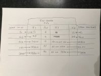
The 3.3v shunt draws a constant 155ma...
So a 18 ohm r drop at the shunt input will dissipate 0.43w times two pr board.
space is limited between the boards in the stack.
I am tempted to follow Doedes first suggestion : set Vin at 10V
I am already feeding my first dddac from chokeinput to -salas sslv1.3 shunt reg. Not worried about the Vin rising to damaging levels.
Ps. Thanks for the replies about experiences with different regulators. Much appreciated. As you know the "powered by Tent" version has space around each LF33 marked as "optionaldiy shuntregulator". I assumed the Tent 3.3v shunt reg was intended to replace the LF33's.
Last edited:
@Simon.
Your diagram is correct if you need to take 5v from dddac mainboard to waveios i2s isolated side. . If you have a dedicated psu hooked up to J3 header on ians fifo, you can skip 5v and gnd on pin 2-6 on J2.
From J7 to mainboards i2s, you only connect pin 12,35 and 40 + one of the many gnd pins, f,ex 6 or 39,,,,
Hello,
Choke input with a high dcr value big choke will force you to think about how things can be done safely
First there is the use of a bleeder resistor that will stop the dc voltage at the first capacitor going up to the same value as if there is no choke at all.
Of course if there are 4 boards with each tent shunts and you use the BIG choke i am using there will be a big voltage drop on the choke so i am still using the 7810 regulators.
Guido Tent told me a big power zenerdiode can stop the voltage rise just in case there is no load present at all.
Because the zener will only act if there is something wrong it will not have negative effects when everything is working as it should.
I remember some years ago when i was just reading this thread and waiting for the boards with the shunts on board waiting to appear there were some people busy with chokes. Power supply changes are not that difficult and the results can be great compared to the money invested.
What i like about chokes is that if properly used they will work and have infinite lifetime.
Greetings, Eduard
Attachments
https://www.tentlabs.com/Components/Shuntcomp/assets/ShuntAppNoteAN04V02.pdf
The 3.3v shunt draws a constant 155ma...
So a 18 ohm r drop at the shunt input will dissipate 0.43w times two pr board.
space is limited between the boards in the stack.
I am tempted to follow Doedes first suggestion : set Vin at 10V
I am already feeding my first dddac from chokeinput to -salas sslv1.3 shunt reg. Not worried about the Vin rising to damaging levels.
Ps. Thanks for the replies about experiences with different regulators. Much appreciated. As you know the "powered by Tent" version has space around each LF33 marked as "optionaldiy shuntregulator". I assumed the Tent 3.3v shunt reg was intended to replace the LF33's.
sorry, I just realized, I was to quick and forgot that the shunt in standard form draws so much current. So my suggestion with 100 Ohm would be too much of course. so (also according Guido Tents application note you should take 22 Ohm in this case. which will draw 0,5 Watt
I left space and suggestion for other regulators as so many people like to experiment with this - Nevertheless the differences are minimal - hence I decided to not add another (expensive and current consuming) shunt regulator at the 3.3 V position
@Simon.
Your diagram is correct if you need to take 5v from dddac mainboard to waveios i2s isolated side. . If you have a dedicated psu hooked up to J3 header on ians fifo, you can skip 5v and gnd on pin 2-6 on J2.
From J7 to mainboards i2s, you only connect pin 12,35 and 40 + one of the many gnd pins, f,ex 6 or 39,,,,
I just started exactly like this yesterday and will continue today 😛 - so I had to think about this also
my thoughts - assuming you want the IAN Fifo to do the isolation, you can feed the IAN form the DDDAC mainboard (10 pin header) - but you have to cool the LF50 (!!!) - or you give the IAN Fifo a separate 3,3V or 5V supply (Ian "suggest" batteries for this - everyone can make his own choice of course)
The WaveIO is than behind the isolation fence seen from the mainboard, so in that case I would not use the 5 Volt supply from the mainboard !
What I will do is using the 5 Volt from the Waveio itself to also feed the isolator output part on the WaveIO - of course this will make it un-isolated but that is now what the IAN is doing. At least for starters…
Of course you can give the WaveIO another own 5 Volt (or 3,3 V ) supply ate the isolation output side. This will give you double isolation, for whatever that is worth. As said I will not start with that, keeping things simple
will report back soon on my results with the IAN ( I also have the set of super clocks to compare)
Last edited:
@Simon.
Your diagram is correct if you need to take 5v from dddac mainboard to waveios i2s isolated side. . If you have a dedicated psu hooked up to J3 header on ians fifo, you can skip 5v and gnd on pin 2-6 on J2.
From J7 to mainboards i2s, you only connect pin 12,35 and 40 + one of the many gnd pins, f,ex 6 or 39,,,,
Thanks 🙂
I did think the 5v was not needed on J2 but your post number 7309 stated this but you probably was not aware I will use a dedicated supply as I have a spare DDDAC 5v PSU I can use.
So I have updated the attached which I feel is now correct, agreed?
Attachments

I just started exactly like this yesterday and will continue today 😛 - so I had to think about this also
my thoughts - assuming you want the IAN Fifo to do the isolation, you can feed the IAN form the DDDAC mainboard (10 pin header) - but you have to cool the LF50 (!!!) - or you give the IAN Fifo a separate 3,3V or 5V supply (Ian "suggest" batteries for this - everyone can make his own choice of course)
The WaveIO is than behind the isolation fence seen from the mainboard, so in that case I would not use the 5 Volt supply from the mainboard !
What I will do is using the 5 Volt from the Waveio itself to also feed the isolator output part on the WaveIO - of course this will make it un-isolated but that is now what the IAN is doing. At least for starters…
Of course you can give the WaveIO another own 5 Volt (or 3,3 V ) supply ate the isolation output side. This will give you double isolation, for whatever that is worth. As said I will not start with that, keeping things simple
will report back soon on my results with the IAN ( I also have the set of super clocks to compare)
Looking forward to your feedback 😀
«What I will do is using the 5 Volt from the Waveio itself to also feed the isolator output part on the WaveIO.»
That is exactly how I did it Doede. Ian’s fifo’s isolated J7 will do the magic.
Ian’s fifo with the stock clocks is performing better than Kali, but with the Accusilicon clocks, everything sounds better.
Looking forward to hear what you think Doede.
That is exactly how I did it Doede. Ian’s fifo’s isolated J7 will do the magic.
Ian’s fifo with the stock clocks is performing better than Kali, but with the Accusilicon clocks, everything sounds better.
Looking forward to hear what you think Doede.
I think it is important to separate 5v from waveio and 5v out from mainboard. If not, waveio will be on the same side of the fence as fifo’s isolated side. I only connect the i2s lines +gnd from J7 - i2s mainboard. J7 have dedicated 5v psu.
Doede, can you confirm if my thoughts about 5v between waveio and 5v on mainboard are correct ? As I see it, only i2s lines + gnd, from J7, shall be connected to mainboard, and fifo powered by a clean psu (J-5 header).
Doede, can you confirm if my thoughts about 5v between waveio and 5v on mainboard are correct ? As I see it, only i2s lines + gnd, from J7, shall be connected to mainboard, and fifo powered by a clean psu (J-5 header).
- Home
- Source & Line
- Digital Line Level
- A NOS 192/24 DAC with the PCM1794 (and WaveIO USB input)