It should also be noted that the dipole axis was aligned along a line from the corner of the room to the listener. With such an alignment the dipole is capable of exciting all room modes, indicating that in reality, with the speaker angled towards the listener, dipoles don't exhibit the claimed immunity to excitation of certain modes.
Solution = don't do that!
Dont toe in your dipole speaker
Don't design your dipole speaker so that it needs to be toed in.
Keep the design as constant directivity as is possible, and then whatever axis you listen on you will have the same tonal balance.
No, and I believe you implied in an earlier post that this discussion applies below the modal range and where the room is acoustically small.Please don't confuse sound propagation with room pressurization.
A net pressurisation cannot exist unless the speaker can hold that pressure, as a monopole can in a sealed room (eg at DC), but an OB cannot produce velocity and expect it to manifest as pressure in an acoustically small environment because it involves a net pressure of zero, although modes could keep such behaviour isolated in space to allow it.
Pressurisation may just be a fancy way to say that you won't get low bass from an OB under these conditions.
Are you able to post polar plots, sorry, if you already have I missed them?Keep the design as constant directivity as is possible, and then whatever axis you listen on you will have the same tonal balance.
Are you able to post polar plots, sorry, if you already have I missed them?
Unfortunately I don't have polars for this loudspeaker - it's winter here and I never set up the finished speaker outdoors where I can get a long time record and good resolution. I did take lots of on and off axis measurements on the drivers individually before building the loudspeaker to vet them. After assembling the speaker I only took a set of on axis measurements that I used to design the crossover with my ACD tools (it's a measurement based active crossover designer). After the crossover was implemented I only did quick on-axis and 20-30 deg off axis measurements to double check things.
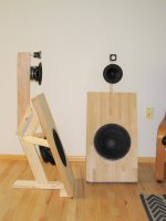
This speaker would likely show some warts under close inspection - there will be increasing directivity around the crossover between the large mid and the tweeter, because of the size of the mid driver for example. The system was more to answer the question of whether I could pull off a nude 3-way system that met my 20-20k dipole goal. It also represents a low-cost design in some respects - I certainly did not use any exotic/expensive drivers. It really was meant to be a sort of a jumping off point for the next iteration of the design. In the next version I am planning to use a planar midrange and tweeter, which I have in hand now, and this should help to improve the performance around 1-2k Hz.
I am simultaneously going to reinvent my system from 2014 (see attached) by drawing on some thing I have learned since that time. I will hang the main baffle and drivers instead of supporting them from the floor, and use the back-to-back dome tweeter in place of the small fullranger. I am pretty optimistic that this will result in some nice improvements all around to the speaker.
Attachments
you can use Neo3 tweeter with removed back cup as true dipole tweeter instead of two back to back tweeters
worked for me...
worked for me...
Solution = don't do that!
Dont toe in your dipole speaker
Don't design your dipole speaker so that it needs to be toed in.
Keep the design as constant directivity as is possible, and then whatever axis you listen on you will have the same tonal balance.
Except both SL and I agreed that they should be toed in slightly:
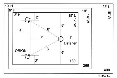
ORION separation is 8'. They are slightly towed in. The listener is at the apex of an equilateral triangle. Distance to the wall behind the speakers is 4', and to the side walls 2'.
An interesting/valient attempt 🙂, but too much of a leap perhaps, the tweeter seems crossed too low?This speaker would likely show some warts under close inspection - there will be increasing directivity around the crossover between the large mid and the tweeter, because of the size of the mid driver for example. The system was more to answer the question of whether I could pull off a nude 3-way system that met my 20-20k dipole goal. It also represents a low-cost design in some respects - I certainly did not use any exotic/expensive drivers. It really was meant to be a sort of a jumping off point for the next iteration of the design. In the next version I am planning to use a planar midrange and tweeter, which I have in hand now, and this should help to improve the performance around 1-2k Hz.
Hang them so you get a better null towards the floor?I am simultaneously going to reinvent my system from 2014 (see attached) by drawing on some thing I have learned since that time. I will hang the main baffle and drivers instead of supporting them from the floor, and use the back-to-back dome tweeter in place of the small fullranger. I am pretty optimistic that this will result in some nice improvements all around to the speaker.
Except both SL and I agreed that they should be toed in slightly:
My room is like the smallest one pictured there, but speakers are 7' apart and LP is 5' from them, infact, even more between them I often find preferable. SL also suggested toeing them in so the null is "reflected" to the LP. In a much larger room I can imagine how Charlie suggests could be better.
The reason why I toe-in my dipoles is to get more late reflections and less early ones. This happens best when speakers are on the long wall. I have noticed that many try to dampen the front wall, which will mostly kill the dipole sound IMHO. Diffusing is ok, as well as long distance to FW.
Attachments
Last edited:
Mine are 6' from front wall, no diffusion, it's a thick stone exterior wall. I have considered making some diffusers out of foam core (?) kill two birds with one stone and provide some heat insulation. 😉
I just want to present this figure of the modal response of a dipole and monopole is a hypothetically very small room with Fo = 246 Hz. Below the Fo the monopole response rises towards DC at 12dB/octave due to room pressurization resulting from the ability to excite the DC mode. The dipole can not excite the DC mode, thus the response, while attenuated somewhat, remains flat to DC.
The idea that below the room fundamental the pressure in the room is homogeneous is an approximation to simplify analysis. It works well where it applies, but it does not apply to the dipole case, and it is not even really true for a monopole. The approximation basically assumes that differences in pressure at different points in the room are small compared to the variation in pressure over a cycle, thus they can be neglected. It's not unlike assuming that the speed of sound is constant for acoustics, of that air can be considered incompressible at low Mach number, of that we can ignore relativistic effect and use Newton's law when speeds are much less than the speed of light.
The idea that below the room fundamental the pressure in the room is homogeneous is an approximation to simplify analysis. It works well where it applies, but it does not apply to the dipole case, and it is not even really true for a monopole. The approximation basically assumes that differences in pressure at different points in the room are small compared to the variation in pressure over a cycle, thus they can be neglected. It's not unlike assuming that the speed of sound is constant for acoustics, of that air can be considered incompressible at low Mach number, of that we can ignore relativistic effect and use Newton's law when speeds are much less than the speed of light.
An externally hosted image should be here but it was not working when we last tested it.
Very interesting thread. What you surmise about the the tweeter is a bit in line with what I attempted to do in my current 3-way dipole as far as final response. I'm still planning on a 4-way setup, but when, I don't know. Like you, I'm going to make my own midrange dipole (if my idea works) and have options for the tweeter, dome or ribbon.My guess about what is happening is this:
At "low" frequencies around 1kHz even with the waveguide the radiation is nearly monopole. So placing two back-to-back creates a dipole. At some frequency the pattern should break down because of the distance between the two domes and the size of the waveguide. Modeled as two monopoles, the response should become replete with nulls and other undesirables. But this doesn't happen, and that was quite surprising. Instead the dipole response pattern just continues all the way up until the top end around 18k or so. I think that the increased directivity from the waveguide causes the front and back radiation to no longer interact, and so you just get a front and rear lobe
I, too, want 20-20K dipole response. My current (first) attempt was to get some experience with dipoles. The woofer dipole is two Peerless 10" drivers in an H-frame. The midrange is a single Scan-Speak 15M/4531 on a rectangular baffle, 7-3/4" wide with the tweeter mounted inline above it. Knowing that the tweeter can't be dipole in this scheme, my goal was to have woofer and mid as true dipoles (horizontally) with the tweeter providing a pseudo-dipole response. That is, the front hemisphere using a monopole tweeter should measure as a true dipole would measure. I selected the Vifa DXT tweeter due to the partial horn loading that provides additional sensitivity at its low end with a faster rolloff and (I hoped) a bit of additional directionality. Eliminating tweeter flare, the usual issue for a monopole tweeter, that also integrated well off-axis with the mid in the crossover was the goal.
The first step was to measure raw off-axis responses of the tweeter. I was surprised to find that the DXT still required significant diffraction control on the baffle, something that shouldn't be a significant problem for a true dipole tweeter, or so I suspect. With that out of the way, on to the crossover.
I had a significant advantage when designing the crossover. I'm using The Ultimate Equalizer (UE) from Bodzio Software. It provides nearly perfect matching of raw driver output to meet the target response, phase as well. I'm using it in linear phase mode. Likewise for the woofer low end extension (correction similar to Linkwitz Transform), so that came later.
My next step was to test the UE system response on-axis for a wide variety of crossovers. By changing the crossover selection and measuring immediately, I confirmed that no matter what I selected, the response on-axis would be exactly what was selected. This was limited to the M/T since the W/M crossover would be 250Hz. But this would validate any crossover work for W/M anyway, giving me full confidence for it as well.
As you've probably read at PETT, I then made a series of measured off-axis summed responses for various crossovers. I eventually settled on doing all crossover design testing at 45 degrees off-axis. This was because I knew that what I selected as a crossover for the on-axis would be perfect, so I only needed to evaluate the off-axis. In one evening I made dozens of crossover tests at 45 degrees until I found the result that gave the best off-axis response. I expected it to be high Fc at low order, but it required low Fc at high order, specifically 1200Hz LR8. Fortunately, with the DXT high sensitivity and 8th order highpass, the tweeter isn't stressed at the listening levels I use, even higher than I find comfortable. The 8th order group delay is moot, since the UE can provide linear phase. I've measured it. The same must hold true for the W/M crossover, 250Hz LR8 as well.
So what I have is something akin to what you observed. The tweeter response off-axis mates well with the midrange rolloff in the off-axis, making the system response in the front hemisphere mimic a true dipole system, 20-20K. It lacks the tweeter response in the back hemisphere, of course, but I don't find that to be any worse than my 3-way monopole system that I've recently re-assembled for testing and comparison, at least with regard to the tweeter section.
Dave
Responding the quote in Dave's post, with my NaO Note the wave guide is effective in the lower frequency domain of the tweeter. But for the Note, that that means around 6k Hz. At higher frequency the directivity of the tweeter controls the pattern.
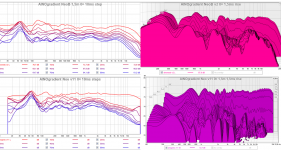
Here is a plot of the axial response of 2 back to back 1" tweeters of a circular baffle. You can see dipole like nulls up to about 10k Hz before the tweeter directivity allows the response to smooth out.

Here is a plot of the axial response of 2 back to back 1" tweeters of a circular baffle. You can see dipole like nulls up to about 10k Hz before the tweeter directivity allows the response to smooth out.
Responding the quote in Dave's post, with my NaO Note the wave guide is effective in the lower frequency domain of the tweeter. But for the Note, that that means around 6k Hz. At higher frequency the directivity of the tweeter controls the pattern.
Here is a plot of the axial response of 2 back to back 1" tweeters of a circular baffle. You can see dipole like nulls up to about 10k Hz before the tweeter directivity allows the response to smooth out.
Hi John,
I recall seeing this back to back dome tweeter design of yours, especially the dipole nulls.
What I found very surprising for my back to back dome-in-waveguide arrangement was the lack of those features, all the way down to 1.5kHz. This allowed me to use the tweeter crossed over very low, under 2kHz. The crossover was something like a high Fc low order one because it also had to flatten the tilt in the response. This sort of crossover provided a lot of attenuation in the lower part of the passband, and the tweeter seemed to be OK like this until you really blasted the level.
Measurement data is posted HERE.
It is very dependent on the tweeters used. For example, here is the response of my NaO II 3-way top end with rear tweeter on and off. There is no significant dipole effect on axis. very little front radiation from the rear tweeter, as shown.

But at 90 degrees there is a big difference in the radiation level with the rear tweeter on or off.

With the NaO Note I went 4 way because above about 1k the 8" mid radiation pattern wasn't sufficiently dipole.

But at 90 degrees there is a big difference in the radiation level with the rear tweeter on or off.
With the NaO Note I went 4 way because above about 1k the 8" mid radiation pattern wasn't sufficiently dipole.
Last edited:
Below the room fundamental the room can be though of as a big, leaky box. So a sealed box woofer is a woofer in a box, in a bigger box. Just as the pressure inside the woofer box changes as the cone moves in and out, the same thing happens in a room below the fundamental due to the net volume change. This can boost bass response below the room fundamental. With a dipole, since the is no woofer box to isolate the rear of the cone, there is no net change in room volume as the cone moves, thus, no pressurization.
Thanks John, Thats a great explanation.... Now I get it!
Pressurisation may just be a fancy way to say that you won't get low bass from an OB under these conditions.
It's an interesting effect. Not too long ago I built an open baffle rig in the garage that used a 21" woofer per side. The woofers played nicely down into the mid 20s before rolling off. I could hear it and measure it. But they didn't really thump as you would mentally expect looked at a couple of 21" woofer in front of you. Clean they were, blow you away they would not.
That was strange for me. I could hear the bass, I could measure the bass, but I could not feel the bass.
Measuring the rear response of just a single tweeter in your arrangement would help show what's happening in the diffraction response of the tweeter for the rear hemisphere.Hi John,
I recall seeing this back to back dome tweeter design of yours, especially the dipole nulls.
What I found very surprising for my back to back dome-in-waveguide arrangement was the lack of those features, all the way down to 1.5kHz. This allowed me to use the tweeter crossed over very low, under 2kHz. The crossover was something like a high Fc low order one because it also had to flatten the tilt in the response. This sort of crossover provided a lot of attenuation in the lower part of the passband, and the tweeter seemed to be OK like this until you really blasted the level.
Measurement data is posted HERE.
The rather severe offset on the plane of the tweeters has to be having a significant effect.
Dave
It is very dependent on the tweeters used. For example, here is the response of my NaO II 3-way top end with rear tweeter on and off. There is no significant dipole effect on axis. very little front radiation from the rear tweeter, as shown.
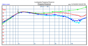
That seems (to me) very surprising. A 1" dome tweeter should be a monopole at 1kHz, even up to several kHz. In the NaO II I think you were using the OX20, which is only a 3/4" dome however, your top plot shows the rear tweeter down around 16dB as measured in front (green trace). How were these tweeters (the OX20) mounted? Was a small baffle used? I haven't seen a pic of the speakers with the grill screen off showing that detail.
Why do you think the rear tweeter output was not more omni and seen in the front? For example, attached is data I found on the web of the OX20 hanging from a string. It's very omni around 2-3kHz whereas your measurements on the NaO II II do not show that.
Pic Legend: Green = 0deg, Red=45deg, light blue=90deg, blue=180deg.
Attachments
Last edited:
- Home
- Loudspeakers
- Multi-Way
- In Pursuit of a 20-20k Dipole Loudspeaker