Hi Brian,
Do you have a POC for your BP6 workbook written up someplace online. I'm seriously considering a build and very much enjoy reading your POC examples as a thorough learning experience.
Cheers.
Not yet. I'm still searching for that "unicorn" BP layout which will give both good results in the passband and good rejection of the "noise" outside of the passband, in a build that's simple to do. So far an offset driver BP4 (like my "Enigma" sub) seems to give those results, but I've already built that, and it's a BP4, not a BP6 or BP8.
Hi Brian,
I modelled up and built my first Box Plan MTH over the last few months.
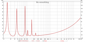
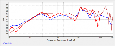
I finished the build today but I'm disappointed to report that the build doesn't match the model. Black is modelled, blue is measured....

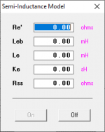
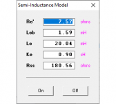
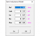
I have two nice drivers that I measured the Semi Le for and used this for my HornResp parameters. I've triple checked all my HornResp parameters and these look fine.
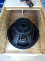
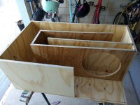
This is my fourth tapped horn build, my first with Box Plan. I used your terrific Box Plan MTH to get a box as small as possible with the target extension I'm looking for which I know will couple well with my room's natural boost.
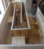
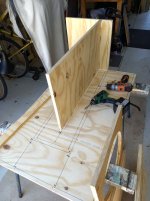
The build was much easier with your charted layout. Picking up the coordinates for the interior horn path was a dream. This made the horn path segments really easy to cut and fit. The enclosure turned out great. I glued with PVA and screwed. It's as tight as a drum.
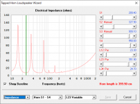
Some attachments on this message. I measured the impedance and overlaid this in DATS with the predicted from HornResp- Blue is modelled, green is measured. REALLY hoping for some help. PLEASE! What have I done wrong?
I modelled up and built my first Box Plan MTH over the last few months.
I finished the build today but I'm disappointed to report that the build doesn't match the model. Black is modelled, blue is measured....
I have two nice drivers that I measured the Semi Le for and used this for my HornResp parameters. I've triple checked all my HornResp parameters and these look fine.
This is my fourth tapped horn build, my first with Box Plan. I used your terrific Box Plan MTH to get a box as small as possible with the target extension I'm looking for which I know will couple well with my room's natural boost.
The build was much easier with your charted layout. Picking up the coordinates for the interior horn path was a dream. This made the horn path segments really easy to cut and fit. The enclosure turned out great. I glued with PVA and screwed. It's as tight as a drum.
Some attachments on this message. I measured the impedance and overlaid this in DATS with the predicted from HornResp- Blue is modelled, green is measured. REALLY hoping for some help. PLEASE! What have I done wrong?
Attachments
-
 Measured.jpg111.5 KB · Views: 104
 -
 LOaded.jpg111.2 KB · Views: 123
 -
 Braced.jpg96.5 KB · Views: 113
 -
 BP-MTH-266.jpg81.6 KB · Views: 253
 -
boxplan-mth-SWS15D4 v2.zip95.5 KB · Views: 79
-
 th alpine.png11.7 KB · Views: 585
 -
Celestion AD15H DATS Modelled = green and Measured = blue Data.pdf340.7 KB · Views: 161
-
 measuring up.jpg137 KB · Views: 89
Last edited:
Some attachments on this message. I measured the impedance and overlaid this in DATS with the predicted from HornResp- Blue is modelled, green is measured. REALLY hoping for some help. PLEASE! What have I done wrong?
The blue graph goes way below the driver's Re of 7 ohms, so I imported the Hornresp model from the workbook and checked the impedance curve in there. It looks very different to the blue graph (see attached image). Did you modify the model after importing it?
Attachments
HI Brian,
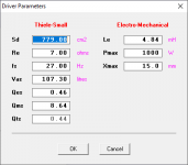
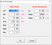
The TS in the BP-MTH are the manufacturers specs. I used these initially.
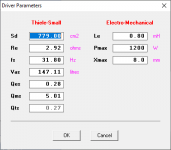
I subsequently DATS the drivers and added the following TS directly into the HornResp model....

Then I did the Semi Le workbook and added these also manually directly into HornResp....

THANK YOU!
The TS in the BP-MTH are the manufacturers specs. I used these initially.
I subsequently DATS the drivers and added the following TS directly into the HornResp model....
Then I did the Semi Le workbook and added these also manually directly into HornResp....
THANK YOU!
Attachments
The measured Le looks very different from the published Le, while the other parameters are similar. I'd recheck that figure.
In any case, the DATS measured impedance curve shows an impedance that drops almost to 3 ohms. The impedance should never go below Re, the coil's resistance. I suggest rechecking all of the driver parameters that you used in the model. I entered the new parameters that you used, and the corresponding impedance curve still does not look like the one that you imported into DATS. The minimum impedance is much higher.
In any case, the DATS measured impedance curve shows an impedance that drops almost to 3 ohms. The impedance should never go below Re, the coil's resistance. I suggest rechecking all of the driver parameters that you used in the model. I entered the new parameters that you used, and the corresponding impedance curve still does not look like the one that you imported into DATS. The minimum impedance is much higher.
Attachments

Hi Brian,
The measured impedance is with my nice old Celestion AD 15H. Apologies for mixing that in with the Alpine data.
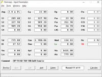
For the Celestion here's the HornResp input screen....

Here's the TS....

Here's the Le....

I haven't measured the Alpine Impedance yet
The measured impedance is with my nice old Celestion AD 15H. Apologies for mixing that in with the Alpine data.
For the Celestion here's the HornResp input screen....
Here's the TS....
Here's the Le....
I haven't measured the Alpine Impedance yet
Attachments
With those new driver parameters, the minimum impedance in the model is around 3.12 Ohms. Your DATS measured impedance curve suggests a minimum impedance for your build that's less than that. Measured minimum impedance should always be more than the modeled minimum impedance, so something's still off.
One other thing to check - make sure that the driver's mount to the baffle is airtight. Even a small leak there will impact low frequency output.
One other thing to check - make sure that the driver's mount to the baffle is airtight. Even a small leak there will impact low frequency output.
Attachments
@Mazza
Unless there are some serious leaks in the box or the driver is broken, you should get SOME Bass out of this, even if the model isn`t optimal... How does it sound? Is there a highpass in the signal by accident?
Unless there are some serious leaks in the box or the driver is broken, you should get SOME Bass out of this, even if the model isn`t optimal... How does it sound? Is there a highpass in the signal by accident?
Brian, my fried, you are a dead-set genius!
So you were right about a high pass.
When I was measuring I was thinking there has to be a high pass on here. All my signal chain checked out for full range tho.
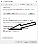
Just now when you mentioned a high pass I had a flash back to some of my first measurement headaches with Win10.....
The dreaded Signal Enhancements check box = a very nasty high pass! Switch this off and Eureka!

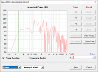
Now we look like this with the SWS....

Sincere apologes for the inconvenience. I truly appreciate your time and help with this.
Tapped horn happiness! Thunder downunder, here we come

So you were right about a high pass.
When I was measuring I was thinking there has to be a high pass on here. All my signal chain checked out for full range tho.
Just now when you mentioned a high pass I had a flash back to some of my first measurement headaches with Win10.....
The dreaded Signal Enhancements check box = a very nasty high pass! Switch this off and Eureka!
Now we look like this with the SWS....
Sincere apologes for the inconvenience. I truly appreciate your time and help with this.
Tapped horn happiness! Thunder downunder, here we come
Attachments
Last edited:
Now we look like this with the SWS....
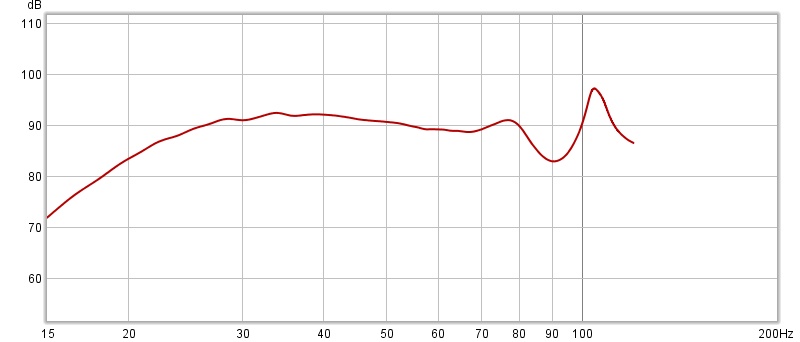
Looks like there's pretty good agreement now between the model and the measured results.
Thanks to all! I'll do some more fulsome measurements and report back.
Brian your Box Plan workbooks are a gift to the world. Seriously I could not, would not have been able to produce a tapped horn to meet my requirements without your tools.
Thank you!
Brian your Box Plan workbooks are a gift to the world. Seriously I could not, would not have been able to produce a tapped horn to meet my requirements without your tools.
Thank you!
Yes they are and I will be doing a few more builds using your Box Planners.
And I realise that you have wisely recommended the tapped horns be built around high efficiency drivers to minimise the relative level of the out of band resonances - BUT the two big 17hz tapped horns I did for a buddy using Alpine Type R's are just sooooo next level in output impact I'm completely addicted.
Feel free to call me a BP-TH Junkie. 😛
I reckon this more compact design with higher efficiency and tuning frequency will lift that to a higher level.
Thanks for feeding my addiction! Now I can self medicate at will.....
Last edited:
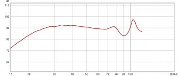
Modelled vs measured impedance for Alpine SWS15D4 and Celestion AD 15H looking good to me per attached.
With the Celestion loaded measured ground plane @ 1m:


With the Celestion loaded measured ground plane @ 1m:
- Brown = modelled
- Black = Omnimic suite measurement
- Red = Omnimic + cal file in REW....
Attachments
Glad it turned out to be so simple and that I could help 🙂Brian, my fried, you are a dead-set genius!
So you were right about a high pass.
BTW, My name´s not Brian 🙂
- Home
- Loudspeakers
- Subwoofers
- Spreadsheet for Folded Horn Layouts...