Is it ok if I use dale rn55 resistors for 1/4w and rn60 for 1/2w? In the data sheet they are rated 1/8 and 1/4w respectively but these are mil specs and I have red somewhere in this forum that for non mil applications the power rating doubles.
It's true that military specs are higher and usually you can use lower rating resistors but using Dale everywhere in HB you won't get expected benefits. I use Dale only in audio path where low noise resistors make sense. Otherwise I use 1W metalized resistors from China bought in larger quantities. They are sufficiently reliable and much cheaper. Use Dale in Mosfet gates (not applicable here) and use quality non-inductive emitter and zoebel resistors. I use Caddock in Zoebel overdoing it a bit.
cheers,
Ok but if I use these resistors I wont have a problem, right?
RN55 are fine.
Industrial and military use different standards. To be more precise on the rating standards:
- in the USA the RN55d / CMF55 are equivalents to an industrial rating with a power rating of 0.50W @ 75C ambient and 0.25W @ 125C ambient, while their military rating is of 0.125W @ 75C ambient and 0.10W @ 125C ambient. The military spec resistors are guaranteed subjected to the full MIL-R-10509/MIL-PRF-55182J test procedures.
cheers,
Hi, I've build the Honey Badger amp for about 6 months. Enjoyed every moment of it. Only today, when I tried powering on the amp, the fuse blew. The fuse that blew was the fuse to the input of my Transformer.
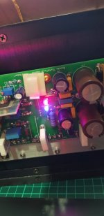
I tried isolating the problem. Seems like the right channel board has some problems. The red LED seems to be flickering and not bright red. The blue LED has no issues. I can hear some cracking sound on the board. I did the test thru a light bulb in series to the input of the transformer. The bias is set to 40mA. I have a pretty large heat sink, hence heat dissipation shd not be a problem.
Now the thing is what component is spoiled. What causes the cracking sound and what causes the Red LED to act this way. Anyone had this problem before. Kindly advice.
Thanks
Sounds like a problem somwhere on the posive rail. Is D8 okei? Or it might be a bad solderjoint somwhere.
Do the 2 channels share PSU? or is it a dual mono build?
Do the 2 channels share PSU? or is it a dual mono build?
Both channels uses isolated PSU. Yes something is wrong with the positive rail, but will need to troubleshoot it. Need to check all solders also n D8.Sounds like a problem somwhere on the posive rail. Is D8 okei? Or it might be a bad solderjoint somwhere.
Do the 2 channels share PSU? or is it a dual mono build?
Ok.. Will need to take out the pcb board to check further. Weird that suddenly this happens.Check your insulators between the outputs and the heatsink.
Ok.. Will need to take out the pcb board to check further. Weird that suddenly this happens.
No need to remove the boards to test for this. Just measure for continuity between the collector of the output transistors and the heat sink.
I've checked every pin of the power transistors. No short circuit. The mica insulators are doing its job.No need to remove the boards to test for this. Just measure for continuity between the collector of the output transistors and the heat sink.
I have also checked D8. How do I know it is faulty?
Here is the board removed. Seems like no burnt components.
Also I am using 4A fuses for the board. Weird thing the fuse on the PCB didn't burnt, but the one at the input stage of transformer burnt.
How I know this channel is faulty. When I disconnect this board, the amp works with the other channel.
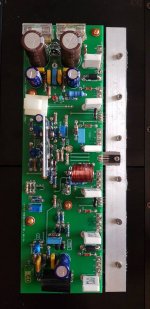
Last edited:
then you need to check transformer rectifier and PSU also.Both channels uses isolated PSU. Yes something is wrong with the positive rail, but will need to troubleshoot it. Need to check all solders also n D8.
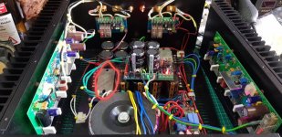
You are right. Seems like the bridge rectifier is no good anymore. Geez. I used a spare PSU n the amp for both channels seems ok now. See the spare PSU with 4 caps and both LEDs are lighted brightly. Fuse does not blow anymore and the heatsinks starts heating up as per normal as I biased the amp at 40mA.then you need to check transformer rectifier and PSU also.
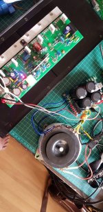
Geez I need to order another bridge rectifier. This lousy recitifer was rated at 20amps at 250volts. As you can see from the first pic, I have 2 of this PSU, one for each channel of the amp.
Any recommended Bridge rectifier which I shd purchase? I thinking of changing both recitiers for left n right PSU filter circuit.
I can't see what type of rectifiers that is used in the PSU. I used dual rectifier with 8 MUR3020 on separate boards in my 5 channel Honey Badger build.
Last edited:
Is this a better setup, that is the build your own bridge rectifier from individual diodes? Would thatI can't see what type of rectifiers that is used in the PSU. I used dual rectifier with 8 MUR3020 on separate boards in my 5 channel Honey Badger build.
1. Ensure a longer lasting PSU.
2. Better sound quality
I bought this rectifier off some Chinese website MDQ 100A rated at 1600v. It came with the PCB. Seems like some cheapo bridge if you ask me.
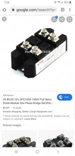
I don't know how much you gain by using fast recovery diodes. I have not messured. Most of my builds are klass A amps. And there i allways use brick bridge.
i would not trust any chepo chinese rectifiers.
i would not trust any chepo chinese rectifiers.
San, do u have a schematic for the PSU which uses the MUR3020?I don't know how much you gain by using fast recovery diodes. I have not messured. Most of my builds are klass A amps. And there i allways use brick bridge.
i would not trust any chepo chinese rectifiers.
50A 1000 volts.....very cheap, a little over U$1....
https://www.lazada.com.ph/products/...l.searchlist.list.47.4cce5200LO42Fc&search=1r
https://www.lazada.com.ph/products/...l.searchlist.list.47.4cce5200LO42Fc&search=1r
- Home
- Amplifiers
- Solid State
- diyAB Amp The "Honey Badger" build thread
