I wanted to look into this project to see if I want to do it. But I have no idea what the hell the BOM file is... I just get chinese characters?
In 2nd message there is a BOM zip file containing an Excel of J2 right channel with content like this:
Reference, Quantity, Value, Spec, Footprint C1 C2 ,2,"10uF","35V Elna SILMIC II","Capacitors_THT:CP_Radial_D5.0mm_P2.00mm" C3 ,1,"10pF","Cornell Dubilier CD5 silver mica","Capacitors_THT:C_Mica_D7.0mm_W2.8mm_P3mm" LED1 ,1,"LED_Small_ALT","","" P1 ,1,"500","Bourns 3386P","Potentiometers😛otentiometer_Bourns_3386P_ScrewTop" Q1 Q2 ,2,"2SJ109","BL grade","TO_SOT_Packages_THT:Toshiba_dual_JFET" Q3 Q4 ,2,"2SK170","GR grade","TO_SOT_Packages_THT:TO-92_Inline_Wide" Q5 Q6 ,2,"SJEP120R100","","TO_SOT_Packages_THT:TO-247_Horizontal_Heatsink" R1 R2 ,2,"10K","Dale CMF55","Resistors_THT:R_Axial_L7.4mm_D2.5mm_P12.70mm_Horizontal" R10 ,1,"0.20 10W","Ohmite TNP10","TO_SOT_Packages_THT:TO-126-2_Horizontal_Clip_Mount" R3 R11 ,2,"100K","Dale CMF55","Resistors_THT:R_Axial_L7.4mm_D2.5mm_P12.70mm_Horizontal" R12 ,1,"22K","Dale CMF55","Resistors_THT:R_Axial_L7.4mm_D2.5mm_P12.70mm_Horizontal" R4 ,1,"15K","Dale CMF55","Resistors_THT:R_Axial_L7.4mm_D2.5mm_P12.70mm_Horizontal" R5 R6 R9 ,3,"100","Dale CMF55","Resistors_THT:R_Axial_L7.4mm_D2.5mm_P12.70mm_Horizontal" R7 ,1,"0.33 10W","Ohmite TNP10","TO_SOT_Packages_THT:TO-126-2_Horizontal_Clip_Mount" R8 ,1,"0.50 10W","Ohmite TNP10","TO_SOT_Packages_THT:TO-126-2_Horizontal_Clip_Mount" U1 ,1,"4N35","","Housings_DIP😀IP-6_W7.62mm"
Reference, Quantity, Value, Spec, Footprint C1 C2 ,2,"10uF","35V Elna SILMIC II","Capacitors_THT:CP_Radial_D5.0mm_P2.00mm" C3 ,1,"10pF","Cornell Dubilier CD5 silver mica","Capacitors_THT:C_Mica_D7.0mm_W2.8mm_P3mm" LED1 ,1,"LED_Small_ALT","","" P1 ,1,"500","Bourns 3386P","Potentiometers😛otentiometer_Bourns_3386P_ScrewTop" Q1 Q2 ,2,"2SJ109","BL grade","TO_SOT_Packages_THT:Toshiba_dual_JFET" Q3 Q4 ,2,"2SK170","GR grade","TO_SOT_Packages_THT:TO-92_Inline_Wide" Q5 Q6 ,2,"SJEP120R100","","TO_SOT_Packages_THT:TO-247_Horizontal_Heatsink" R1 R2 ,2,"10K","Dale CMF55","Resistors_THT:R_Axial_L7.4mm_D2.5mm_P12.70mm_Horizontal" R10 ,1,"0.20 10W","Ohmite TNP10","TO_SOT_Packages_THT:TO-126-2_Horizontal_Clip_Mount" R3 R11 ,2,"100K","Dale CMF55","Resistors_THT:R_Axial_L7.4mm_D2.5mm_P12.70mm_Horizontal" R12 ,1,"22K","Dale CMF55","Resistors_THT:R_Axial_L7.4mm_D2.5mm_P12.70mm_Horizontal" R4 ,1,"15K","Dale CMF55","Resistors_THT:R_Axial_L7.4mm_D2.5mm_P12.70mm_Horizontal" R5 R6 R9 ,3,"100","Dale CMF55","Resistors_THT:R_Axial_L7.4mm_D2.5mm_P12.70mm_Horizontal" R7 ,1,"0.33 10W","Ohmite TNP10","TO_SOT_Packages_THT:TO-126-2_Horizontal_Clip_Mount" R8 ,1,"0.50 10W","Ohmite TNP10","TO_SOT_Packages_THT:TO-126-2_Horizontal_Clip_Mount" U1 ,1,"4N35","","Housings_DIP😀IP-6_W7.62mm"
put this in first line:
SEP=,
then you'll be able to view file in excel with columns
problem is related to windows localization parameters
SEP=,
then you'll be able to view file in excel with columns
problem is related to windows localization parameters
Last edited:
In case anyone else has trouble, here's a capture of the BOM from Kicad:
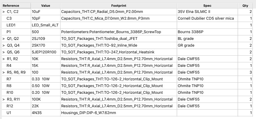
NB: this is for a single channel. Double the quantities for a stereo amplifier.
Note also that each 2SJ109 can be replaced with a pair of 2SJ74, and that one of the SemiSouth JFETs (Q5) can be replaced with a cheaper MOSFET (see the J2 thread).
Cheers,
Jeff.
NB: this is for a single channel. Double the quantities for a stereo amplifier.
Note also that each 2SJ109 can be replaced with a pair of 2SJ74, and that one of the SemiSouth JFETs (Q5) can be replaced with a cheaper MOSFET (see the J2 thread).
Cheers,
Jeff.
Attachments
put this in first line:
SEP=,
then you'll be able to view file in excel with columns
problem is related to windows localization parameters
I run Linux, which has Libre, that can read all the standard formats... I can't understand why you wouldn't make it a standard .xml that is backwards compatible to early versions of excel.
Let me show you.


... why you wouldn't make it a standard .xml...
Because the BOM was written by Kicad, not Excel.
In the Import dialog you show, is there an "ASCII" choice under Import / Character set? I imagine that would give you what you want, although I don't have Excel or Libre....
Change the "Character set": to- Unicode (UTF-8)
yo
That worked, thanks!
SJEP120R063
I missed out on the groupbuy for SJEP120R100 but have some boards coming my way, so trying to source the parts
I could get some SJEP120R063 instead. Could anyone confirm if SJEP120R063 would work in place of SJEP120R100 without modification?
Thanks.
I missed out on the groupbuy for SJEP120R100 but have some boards coming my way, so trying to source the parts
I could get some SJEP120R063 instead. Could anyone confirm if SJEP120R063 would work in place of SJEP120R100 without modification?
Thanks.
Hi Bud,
As I understand it the SJEP120R063s are two 120R100s dies in a single package. They should work fine, but they seem like they'd be a waste without increasing the bias to take advantage of them....
Cheers,
Jeff.
As I understand it the SJEP120R063s are two 120R100s dies in a single package. They should work fine, but they seem like they'd be a waste without increasing the bias to take advantage of them....
Cheers,
Jeff.
Thanks Jeff, and thank you also for preparing the PCBs.
So with the SJEP120R063 could I use the same resistors as your BOM? i.e. the SJEP120R063 wouldn't necessarily require any modification of circuit or other component values (for a standard version).
If I get a big enough chassis I suppose I could up the bias, though I'm more interested in upping the gain than total power.
The important thing with the resistor values is to keep a similar ratio between the top and bottom source resistors. But yes, the same values as spec'ed should work.
You can increase the gain by raising R3 and R11. Depending on how much you increase it, you may need to also increase the phase lead compensation (C3). This will be a trade-off between bandwidth and stability margins.
You can increase the gain by raising R3 and R11. Depending on how much you increase it, you may need to also increase the phase lead compensation (C3). This will be a trade-off between bandwidth and stability margins.
I got curious and ran some sims. Higher gain can definitely use a bit more phase lead comp. (It's probably a little low to start with -- 12p might work better even with the default gain. 15p should keep it stable with higher gains.)
In my sims distortion at 1W was 0.010% at 20dB gain (100K feedback resistor), 0.014% at 23dB (150K feedback resistor), and 0.021% at 26dB gain (220K feedback resistor).
Note: I'm a DIYer, not an expert, and these are just simulations. YMMV. 😉
Cheers,
Jeff.
In my sims distortion at 1W was 0.010% at 20dB gain (100K feedback resistor), 0.014% at 23dB (150K feedback resistor), and 0.021% at 26dB gain (220K feedback resistor).
Note: I'm a DIYer, not an expert, and these are just simulations. YMMV. 😉
Cheers,
Jeff.
What is the bias current approx. of this amp? 1.5 A or so?
Yep.
(My sim says 1.44, but it's not 100% accurate because I don't have a SPICE model for the 4N35.)
OK....I have four Meanwell 4.5A SMPS which I think I will use for this project with some additional filtering. Interesting to see how much capacitive load it can handle before it goes into protection or see how "smart" the error recovery is.
Is it trivial to estimate the voltage gain of the mu-follower output stage just by looking at it? …...if it was just a source-follower it would not need negative feedback to make it linear?
Is it trivial to estimate the voltage gain of the mu-follower output stage just by looking at it? …...if it was just a source-follower it would not need negative feedback to make it linear?
With triodes the gain of a mu follower is just the mu of the bottom triode. If that also holds true for FETs, then the gain should be delta-Vds/delta-Vgs.
Rds-on for the SemiSouth is 0R1 and we have another 0R7 between the rail and the output.
If we look at the transconductance curve we find that a Vgs delta of 1V (2V -> 3V) yields a Ids delta of 19A (14 -> 33). 19A over 0R8 gives 15.2V for a gain of about 15. But this hasn't taken into account the fact that the Ids is also dependent on Vds. How to factor that in probably requires real math (which is above my pay-grade).
Bottom line: I haven't a clue what the answer is.
- Home
- Amplifiers
- Pass Labs
- Long skinny builders thread