Good luck in the real world.
Your Ovation is claimed 480W into 4ohm, your "240 watter" is 240W into 8ohm. It is therefore spot on the calculation I made earlier, where I said that 4 pairs are at the limit for 2ohm load, better 5 or even 6 pairs. With 2ohm and 45 degrees, 6 pairs are good (with a little bit of luck).
The peak output current in a class A amplifier is 2*Iq which gives a peak output voltage of 27V from which you can then calculate the power.
That is correct for push-pull class A.
This design claims to be 39 watt RMS single ended.
Nelson Pass:
A limitation of single-ended Class A operation is that the peak output current is limited to the value of the bias current. By comparison, push-pull Class A can deliver twice the bias current as peak output in Class A, and generally much more than that in Class AB
Rod Elliott describes the approx. requirements for a 20W (continuous) class A amplifier, 8 ohm load:
Load Voltage (at Speaker) 12.65 Volts RMS (17.9 Volts Peak)
Load Current (through Speaker) 1.58 Amps RMS (2.23 Amps Peak)
Supply Voltage +/- 20 Volts (constant)
Supply Current +/- 2.25 Amps (peak)
Last edited:
TT;
Here is my reasoning why CFA often sounds better. It is not because of distortion within 20Khz BW. It is what happens with the HF when it get amplified. Freq above 20KHz if they are within BW of amp will try to amplify them also. If it cannot do it with low distortion, IM products fall within the audio range.
Here is a sample of HF from DAC's which does NOT get all filtered out at the DAC.
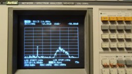
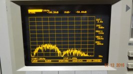
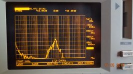
If using/designing a typical high nfb VFA, you will more likely need HF filtering on input.
THx-RNMarsh
Here is my reasoning why CFA often sounds better. It is not because of distortion within 20Khz BW. It is what happens with the HF when it get amplified. Freq above 20KHz if they are within BW of amp will try to amplify them also. If it cannot do it with low distortion, IM products fall within the audio range.
Here is a sample of HF from DAC's which does NOT get all filtered out at the DAC.


If using/designing a typical high nfb VFA, you will more likely need HF filtering on input.
THx-RNMarsh
Last edited:
Here is a sample of HF from DAC's which does NOT get all filtered out at the DAC.
If using/designing a typical high nfb VFA, you will more likely need HF filtering on input.
a) That looks like a really bad DAC with those artifacts in the 10’s of KHz range, are you sure those are strictly from the DAC?
b) What’s bad with input filtering? VFA or CFA both need it to avoid RF ingress, anyway.
Hi Richard,
How about driving the output into a 8 ohms in parallel with 8uF, 1khz square wave at 1/3 power and let us know the results. I sure would like to see the resultant waveform.
I suspect you might have a stability issue.
Regards,
Jam
How about driving the output into a 8 ohms in parallel with 8uF, 1khz square wave at 1/3 power and let us know the results. I sure would like to see the resultant waveform.
I suspect you might have a stability issue.
Regards,
Jam
With 3.4 A pk-pk current?
Can you give me the math?
If you take a look at the sx-Amp write up you will see the output power calculations (about 1/3 rd the way through the doc). But, these calcs assume both the output stage devices are still conducting.
So, I would sim the amp concerned to make sure the standing current is 1.7 A ( looks like it from 0.6/(2*Re) = 0.6/0,44 ) which is the 3.4 A peak into the load I mentioned earlier.
Do-you agree if I try to define this "Sound better" ?Here is my reasoning why CFA often sounds better.
To make a comparison with photography, i should say more focused. Not more sharpness, with all the hardness that comes with-it, on the contrary. It is more fluid in the same time. Like when you use a digital captor of 60MPx and compare with a 42 MPX one. It is a subtle change of character. Less halo around the instruments in the space, better séparation, less interaction between them.
I agree. The only believable explanation I can find. And what reinforces me in this hypothesis is the fact that, when we decrease the cutoff frequency of the low pass filter of the input stage, we can hear a progressive improvement up to the limit point where we start to destroy audible high frequencies.It is not because of distortion within 20Khz BW. It is what happens with the HF when it get amplified. Freq above 20KHz if they are within BW of amp will try to amplify them also. If it cannot do it with low distortion, IM products fall within the audio range.
Strangely enough, but not so much, by decreasing this frequency cutoff, we feel that the level of the treble increases a little. Or rather, their intelligibility.
Anyway, harmonic distortion is not so much a concern. It change slightly the character of instruments, but it can be in a very natural way (tube sound is a good example) as these harmonics are already present in the original sound of each instrument.
Of course, all this is highly subjective, it is difficult to share sensations, and it will probably trigger the usual protests of those who, for some reasons incomprehensible to me, refuse such explorations.
What about phase shift?I agree. The only believable explanation I can find. And what reinforces me in this hypothesis is the fact that, when we decrease the cutoff frequency of the low pass filter of the input stage, we can hear a progressive improvement up to the limit point where we start to destroy audible high frequencies.
But this won’t help much if the amp bursts into oscillations, which I believe is what’s happening to yours, as the root cause for the crash and burns. You and Dadod are learning the hard way, on your time and dime, a classic lesson: there is no free lunch when it comes to negative feedback. Which is: for any fixed frequency compensation order (2, in your case) increasing the loop gain (that is, ultra low distortions) always comes with a stability penalty, there is no way around.
I design CFA with OITPC compensation like Dadod, but using vertical mosfet. My design slightly different. One using 1 pair and other using 2 pairs, all using 35VDC. Until now, they never had problem. They tested using many speakers.
Very good question ;-)What about phase shift?
I believe it is part of the landscape. With all the progress we had made in electronic and the knowledge that comes with, i'm astonished by our lack of knowledge in psycho acoustic.
This is the reason for the debates -often heated- on the forum. Between those that the measurements numbers reassure, without knowing the impact they really have on our feelings, and those who privilege these feelings, sometimes neglecting the scientific achievements.
In confidence, for having worked on the both sides of the fence, in r&d offices and behind mixing desks, I have always tried, without much success, to create a bridge in my mind between these two worlds.
It gives an unpleasant feeling to know nothing, and sometimes, the happiness of achieving something, despite this.
I often envy those who think things are so simple because they master a small part of the all landscape.
As our life is short, and our minds limited, it look impossible to plow a large area and dig deep at the same time.
[Edit]One of the reasons I do not care so much about "blind listening" is that I feel myself blind enough without it ;-)
Last edited:
a) That looks like a really bad DAC with those artifacts in the 10’s of KHz range, are you sure those are strictly from the DAC?
b) What’s bad with input filtering? VFA or CFA both need it to avoid RF ingress, anyway.
Probabaly the DAC and its shifting effects of noise and distortion/artifacts above 20KHz. This is simply measured at the analog output of CD players.
It does not hurt anything to have HF filtering on both types. but usually isnt done on either type. Or not low enough freq to matter.
The CFA amp is linear and fast enough (SR) to have little distortion at HF freqs. Not so with VFA with increased distortion as fb is reduced at HF.
This is the topology of my choise today and variations of it.
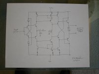
BTW -- All M. Levenson amps/preamps have been band limited since forever. A key contributor to why they sound better in most systems. 🙂
Originally, put there to prevent triggering TIM, but now useful to remove digital artifacts, also.
You're welcome.
THx-RNMarsh
Last edited:
Recently, I had a pre-release dac sent by a manufacturer wanting a listening evaluation by Jam and me. Found that it had 19.1 MHz common mode RF at the output from a DC-DC converter on the board. The manufacturer only measured for differential noise and completely missed the CM issue. The RF produced a bit of audible distortion in our Neurochrome HP-1 headphone amp, which is what led to a search for the cause.
As mentioned before Rupert Neve and Manfred Schroeder both consider the limit of perception at 5 degrees of phase shift at 20,000 hertz. They used different methods to reach their conclusions at different locations and independently.
My attempts to find my perception limits were quite a bit lower.
An easy test to do these days with computer generated waveforms.
RNM,
Looking at your amplifier problem, you migh consider raising the voltage to the voltage amplifier stage and drivers. Then you can lower the output rails voltage. This should move you into the SOA without reducing the output power. At 60 volt rails 20 amps would still be within the ratings. Although you might still have a problem with loudspeakers that do not comply with either the IEC or AES loudspeaker impedance rating methods. But should handle most rational designs.
The second issue would be fusing to protect the amplifier in case of silly loads. This could be done by just a power line fuse if a soft start circuit is used.
I do not prefer the common versions of reducing input current until operating voltages are reached. That is because the current reduction method often requires a resistor and it is very rare to find one that can really handle the surge and is rated for such use by safety agencies. The other method of using semiconductors to ramp things up is just more complicated than I like.
My simple stupid method is to use two fuses. The start-up fuse is a time delay type that can handle the surges. There is a second operating fuse in series that is shunted by a relay until the rails voltage stabilizes. The same relay driver circuit can also then open the input mute relay! Uses all rated parts and allows for much more critical fusing. BTY the operating fuse is best left hidden in the case.
What do all those have to do with sound replaying system?This is the reason for the debates -often heated- on the forum. Between those that the measurements numbers reassure, without knowing the impact they really have on our feelings, and those who privilege these feelings, sometimes neglecting the scientific achievements.
In confidence, for having worked on the both sides of the fence, in r&d offices and behind mixing desks, I have always tried, without much success, to create a bridge in my mind between these two worlds.
It gives an unpleasant feeling to know nothing, and sometimes, the happiness of achieving something, despite this.
I often envy those who think things are so simple because they master a small part of the all landscape.
As our life is short, and our minds limited, it look impossible to plow a large area and dig deep at the same time.
[Edit]One of the reasons I do not care so much about "blind listening" is that I feel myself blind enough without it ;-)
Good old Bryston includes a sub-two-ampere "signal relay" in each amp channel. During power up, and soft start, and power down, and any time the output is muted, these relays short out the bias spreader circuit (a/k/a "VBE multiplier"), resulting in zero DC current in the driver transistors and output stage transistors. A pleasing way to avoid trouble when your conditionally stable amplifier has janky supplies and is thus in the conditionally stable regime.
_
_
Last edited:
In non-scientific listening comparison, right?A key contributor to why they sound better in most systems. 🙂
EH,
My frustration stems from being able to identify effect but not having enough knowledge to identify cause.
Yours oth seems to stem from knowing the cause but not comprehending the effect.
I’m kindly understanding where your coming from.
My frustration stems from being able to identify effect but not having enough knowledge to identify cause.
Yours oth seems to stem from knowing the cause but not comprehending the effect.
I’m kindly understanding where your coming from.
Mark Alexander did the same in his famous CFA design.relays short out the bias spreader circuit (a/k/a "VBE multiplier"),
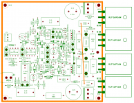
One day I will fab this design just for the fun of it. Once I clear off all the other projects on my plate 🙂 Esp now that pcb's are so cheap when you make them 100x100mm. lateral mosfets are not so cheap however.
Duh, I go looking for the Coto relay in that layout and it is not there 🙂 That's okay, the source resistors can go, told they are of no use in a latfet design, so can the IV limiter, makes a lot more room to put the relay in there, its been a few years since I looked at this design. I did few versions of this design, might have gotten lost in HDD crash years ago.
It would be a thrill to put RM & JC in room, change out amplifiers, without knowing what is what and test out their assumptions. Time is marching along.
Attachments
Last edited:
My 300V/us VFA still seems to manage quite well so I'm in the camp who doesn't see the magic of CFA.
That is correct for push-pull class A.
This design claims to be 39 watt RMS single ended.
Nelson Pass:
A limitation of single-ended Class A operation is that the peak output current is limited to the value of the bias current. By comparison, push-pull Class A can deliver twice the bias current as peak output in Class A, and generally much more than that in Class AB
Rod Elliott describes the approx. requirements for a 20W (continuous) class A amplifier, 8 ohm load:
Load Voltage (at Speaker) 12.65 Volts RMS (17.9 Volts Peak)
Load Current (through Speaker) 1.58 Amps RMS (2.23 Amps Peak)
Supply Voltage +/- 20 Volts (constant)
Supply Current +/- 2.25 Amps (peak)
You are quite correct - sorry I overlooked that.
On single ended systems, you have a 'hard stop' on the side with the current source. On push pull designs like the sx or kx-Amp, the amp simply transitions to class AB. Both the sx and kx Amps will deliver 50W into 4 Ohms class AB while the kx can deliver >80W into 2 Ohms with commendably low distortion.
But, please have this discussion with the Nirvana guys - I've stuck my oar into their effort enough already - the design is simple and quite elegant.
- Status
- Not open for further replies.
- Home
- Member Areas
- The Lounge
- John Curl's Blowtorch preamplifier part III
