That one cut plane is the horizontal?
Do you mean it's the cross-section of the horizontal expansion, and therefore the wavefronts in #4535 are actually "observed" from the (cross-sectional) right side of the horn, as suggested by its position?
Sorry, but I think that I did not understand your question. Anyway, don't be confused. These are two completely different horn calculations for h and v. Here you only see the horz. horn. I had the idea to blend the two horn profiles some days ago and it worked quite nicely just after having programmed it.
Sorry, but I think that I did not understand your question. Anyway, don't be confused. These are two completely different horn calculations for h and v. Here you only see the horz. horn. I had the idea to blend the two horn profiles some days ago and it worked quite nicely just after having programmed it.
Ignore my last post. Judged by the shape of construction wave fronts, more specifically at the mouth edge, it has to be the horizontal.
Peter says
In his own build thread, Peter also says
lol
I propose new thread title "Is it procrastination to reach 4,500 posts without any result"
In his own build thread, Peter also says
After one year, they're finally finished.
lol
The JMLC HVDiff is right at the biggest dimensions I'd like to go. I see you were speculating more versions with roll overs, and what not. I think if I were to choose this horn for creation that I'd like the "mini roll-back or lip to a terminated mouth horn" that you brought up about applying to the jericho and shark.
I have used soft termination at the horn mouth that had easily measurable improvements - audible too, but not "night and day." Always keeping Mr Iwata's slotted horns in mind I've tried going from a dense to a loose soft edge.
But I didn't pursue that enough to know if it really helped.
I've heard that type of solution (foam, towels, etc) in other few places. I could characterize the lossy surface then add it to the model. I would prefer a surface less prone to contact damage.
As you know =) these dimensions are satisfactory. This is easily the perfect horn for me to cross at 300hz, in theory. Maybe when Don gets a chance, he can run sims.
Devils Advocate.....without breaking the 300hz or lower request. Is this the horn you would choose? Why or why not. The drba_Shark_RA_45_PE_PRJ @ drba_Jericho_45_PE (pg 449) are not exactly miles away from ideal...is there anything that we haven't tried that is worth the effort, like the round overs on the lip. The original Jericho is really close, but suffers from the diffraction, would the radius on the lip fix the diffraction on the lip here too?
This is directed towards who ever is inclined to answer... YouTube
The original "jericho" would be a good candidate for some CAD modifications to see the impact of adding a round over or some mouth treatment.
Slots or holes might be a good choice there.I would prefer a surface less prone to contact damage.
Attachments
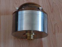
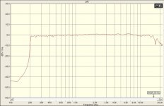
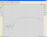
Pretty impressive frequency response of a field coil compression driver with Aluminum diaphragm.
Measurements taken at the throat of the driver, without horn, 1/24 octave spectra with a 16 Ohms diaphragm at 1 Watt (4.0 Volts RMS) sweep sinusoidal signal from 200Hz to 22,000Hz.
One driver would buy you 3 pairs of Axi2050 though.
Measurements taken at the throat of the driver, without horn, 1/24 octave spectra with a 16 Ohms diaphragm at 1 Watt (4.0 Volts RMS) sweep sinusoidal signal from 200Hz to 22,000Hz.
One driver would buy you 3 pairs of Axi2050 though.
Attachments
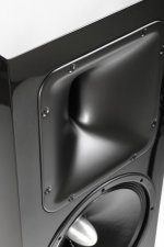
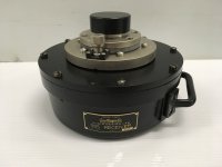
AE TD12 + XR1564 + ND4015Ti2 (Tin Coated).
Attachments

Last edited:
Pretty impressive frequency response of a field coil compression driver with Aluminum diaphragm.
Measurements taken at the throat of the driver, without horn, 1/24 octave spectra with a 16 Ohms diaphragm at 1 Watt (4.0 Volts RMS) sweep sinusoidal signal from 200Hz to 22,000Hz.
That can't be real. There has to be a roll off above the mass break point of the diaphragm. Just like you would see in a plane wave tube measurement.
Rob🙂

This accompanying statement is from the website:
"Measurements taken with color identifying curves at the following field coil applied potentials:
Orange 10V
Green 20V
Blue 25V
Red 30V (do not apply higher than 31Volts potential for continuous use)
The driver may be operated with a field coil voltage from 24 to 30 Vdc.
Operating preferred voltage 28 Volts DC
The magnetic field strength is directly proportional to the power applied to the field coil up to saturation where an increase of power to the field coil won't increase the strength of the magnetic field and all that extra energy will be wasted as heat. In this configuration the best compromise is at 28 Volts dc, keeping the heat generation at a minimum with a very flat and high efficiency output throughout the audio response of the driver, extending very well up to he higher frequencies. This frequency response is rarely accomplished with permanent magnet drivers.
The frequency response clearly deteriorating as the power to the coil is reduced specially at the top end of the frequency spectrum as shown in the orange colored curve, the response is very similar with 28 to 30 Volts applied, only showing a relatively small increase of output at the frequency extremes at higher Voltages."
Those curves look too good to be true, yet I don't think these are beyond what's possible.
At almost $6000 each it should outperform just about any similar sized driver.
I.e. the response of a S2 (without distortion figures) is also very impressive and better than 90% of the pro audio stuff.
The same goes for WE and some RCA drivers.
The plots are probably normalized and the green curve clearly shows mass break(up) at 4 and >8k.
Last edited:
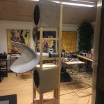
Interesting pic. I'm not dropping hints, I like your horn better Doc and Don!
I am aiming for S2 like performance then Ro808?
I am aiming for S2 like performance then Ro808?
Attachments
Last edited:
Interesting pic. I'm not dropping hints, I like your horn better Doc and Don!
I am aiming for S2 like performance then Ro808?
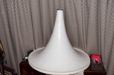
No problem, these jmlc Iwatas have their own beauty! The most interesting question is, although, what is between the driver and the horn? Is this a very long linear section?
Line Magnetic LM-555 (WE-555 clone) with 20uF cap in series on AH160 JMLC horn, mic 0.75m back on centre line.
Attachments

Interesting pic. I'm not dropping hints, I like your horn better Doc and Don!
I am aiming for S2 like performance then Ro808?
I guess you do. Even though many S2 addicts (Romy et al.) argue not to use it >6000hz, I know of at least one high-end loudspeaker manufacturer who told me it's fine up to 17k.
I hold this guy's opinion the highest regard.
At the same time we have to bear in mind that a S2 is not an Axi2050.
The magnetic field strength is directly proportional to the power applied to the field coil up to saturation where an increase of power to the field coil won't increase the strength of the magnetic field and all that extra energy will be wasted as heat. In this configuration the best compromise is at 28 Volts dc, keeping the heat generation at a minimum with a very flat and high efficiency output throughout the audio response of the driver, extending very well up to he higher frequencies. This frequency response is rarely accomplished with permanent magnet drivers.
Why are the units in the graph dbv for an acoustic measurement?? You can't defy physics,
JBL Technical Notes Volume 1 Number 8
Rob🙂
- Home
- Loudspeakers
- Multi-Way
- Is it possible to cover the whole spectrum, high SPL, low distortion with a 2-way?