Hi Vunce,
Superb build!!! Can't wait to read your listening impressions after the burn in.
All the best!
Do
Superb build!!! Can't wait to read your listening impressions after the burn in.
All the best!
Do
Thanks Fellas for the encouragement and all the kind words 🙂
It’s a big part of what makes this forum so cool, we all pull for a common interest.
@Meanie,
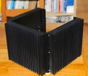
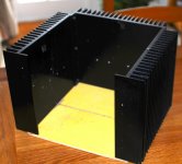
I like the shape of the heatsinks also. Angular and curvy 😀
There is a lot of volume inside the chassis, but with only 10.5” x 11.5” workable floor space, components get tight quickly.
@Harry3,
Yes, the only way to get a dual mono psu with capMx to fit in the limited space was to utilize the SLB. Counting the heatsink fins the overall footprint is nearly 17” wide, I didn’t want to go any wider.
@Zman01.
I’ve got some ideas for the finishing the wood work already, but I’ll probably ask for some opinions.
In time, I’m sure there will be a few listening impression updates.
Cheers,
Vunce
It’s a big part of what makes this forum so cool, we all pull for a common interest.
@Meanie,
I like the shape of the heatsinks also. Angular and curvy 😀
There is a lot of volume inside the chassis, but with only 10.5” x 11.5” workable floor space, components get tight quickly.
@Harry3,
Yes, the only way to get a dual mono psu with capMx to fit in the limited space was to utilize the SLB. Counting the heatsink fins the overall footprint is nearly 17” wide, I didn’t want to go any wider.
@Zman01.
I’ve got some ideas for the finishing the wood work already, but I’ll probably ask for some opinions.
In time, I’m sure there will be a few listening impression updates.
Cheers,
Vunce
Vunce,
Those are slick looking heatsink fins. Where do you get those? I like your sort of cube shape amp. It’s not a common shape in a Class A amp.
Those are slick looking heatsink fins. Where do you get those? I like your sort of cube shape amp. It’s not a common shape in a Class A amp.
Hi X,
I pick them up from eBay, I believed they were reclaimed heatsinks from solar power inverters. It’s deceiving in the pictures, it does look like a cube but if you looked at the footprint from the top it’s definitely wider than deep. (17” x 12.5”)
I pick them up from eBay, I believed they were reclaimed heatsinks from solar power inverters. It’s deceiving in the pictures, it does look like a cube but if you looked at the footprint from the top it’s definitely wider than deep. (17” x 12.5”)
Hi Vunce
This is a very nice build!
You also have a very good power supply from what I can tell. With your heatsinks you could probably increase even more the bias if you have 4 ohms speakers but with your speakers efficiency it may not worth it because you will never use that amount of power I suppose. Anyway you still can run in class AB at very high power level. With 8 ohms speakers you are already in full class A up to 25Wrms.
Keep us posted on your final build with the wood it should be nice looking...😉
Fab
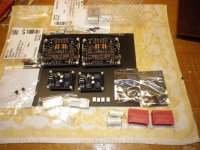
Back to the drawing board, stripped out all and going for twin Mono PS.

I don't have much space, so going double-decking SLB.
I don't have much space, so going double-decking SLB.
Back to the drawing board, stripped out all and going for twin Mono PS.
I don't have much space, so going double-decking SLB.
I highly approve and endorse your efforts! Always go dual mono!
Will be taking a similar route! I already have x2 of these Krell Clone chassis! Was thinking of using two heatsinks with a 5mm top, bottom and rear panel and 11mm front panel. These should make x3 stereo amps
The individual sinks are 220mm x 24mm net of flanges and are 40mm fins + baseplate (8mm plate).
Is this enough cooling for one board per heatsink?
Thanks.
The individual sinks are 220mm x 24mm net of flanges and are 40mm fins + baseplate (8mm plate).
Is this enough cooling for one board per heatsink?
Thanks.
Attachments
Hi Meanie,
That vertical stacking setup looks great. However, you may want to consider a non-conductor instead of the thick aluminum rod holding the two toridal trafos together. I am not sure how much magnetic flux there is in the middle of the toroid but an aluminum rod, due to its high electrical condutivity can get heated up due to eddy currents and this will sap your power. Magnetic eddy current brakes often use aluminum or copper plates next to magnets. The magnetic field at the center of a toroidal wrapped trafo is zero, however, it is not zero as you get away from the center. A skinny steel bolt is fine as it is small and close to the center. But a thick rod picks up more non-zero field (as some point it is the same as the main toroid at the other extreme).
That vertical stacking setup looks great. However, you may want to consider a non-conductor instead of the thick aluminum rod holding the two toridal trafos together. I am not sure how much magnetic flux there is in the middle of the toroid but an aluminum rod, due to its high electrical condutivity can get heated up due to eddy currents and this will sap your power. Magnetic eddy current brakes often use aluminum or copper plates next to magnets. The magnetic field at the center of a toroidal wrapped trafo is zero, however, it is not zero as you get away from the center. A skinny steel bolt is fine as it is small and close to the center. But a thick rod picks up more non-zero field (as some point it is the same as the main toroid at the other extreme).
Oh i know its conductive but not magnetic.
I will machine a Delrin replacement then, thanks for highlighting it.
I will machine a Delrin replacement then, thanks for highlighting it.
I’ve been working on the finishing details for my USSA5 amp and took a shot at salt water aluminum etching. I think this technique has real potential for the look I’m going for.
With some real stencil work the name plate should look pretty cool 😎
With some real stencil work the name plate should look pretty cool 😎
Attachments

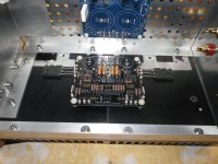
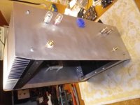
Made some progress today. I hope my USSA5 can be singing next week.
I use back the 18Vac trafos due to space constraint, still able to achieve +/- 23.2 Vdc @ 1.4A

I use back the 18Vac trafos due to space constraint, still able to achieve +/- 23.2 Vdc @ 1.4A
Last edited:
Meanie,
Looking good - hopefully you can tie up everything soon.
Btw, the you are getting decent DC voltage with the SLB and 18VAC trafo with 1.4A bias!
Looking good - hopefully you can tie up everything soon.
Btw, the you are getting decent DC voltage with the SLB and 18VAC trafo with 1.4A bias!
Hello to everyone...
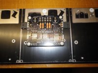
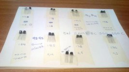
Ι would like your opinion about the mosfets mounting on the heatsink.
in case if needed to add another module heatsink to reach the length 41cm X 15cm x 4 cm, you see the temperature in Greece in the summer it reaches 33 C.. room temp
Ιn the first photo, it is too long to mount the mosfets? the drivers stays as they are?
I don't like to squeeze the legs mosfets as the second photo ...
Μy priority is to not use it at all the C1..
Attachments

Last edited:
Made some progress today. I hope my USSA5 can be singing next week.
I use back the 18Vac trafos due to space constraint, still able to achieve +/- 23.2 Vdc @ 1.4A
Very nice Meanie
1.4A COOOL
Im waiting your results temp ?
Also and the most important SLB vs CRC if you have the opportunity....
Regards Nikos
@Zman01, we do have pretty good main supply from the PowerCompany here in Singapore.
@Nikosokey, Sorry for the confusion. I loaded the SLB with a resistive load and adjust for 1.4A. Because due to double decking SLB, i got no way to adjust the voltage once everything is installed.
My Ussa5 is running at 1.3A.
This chassis has a smaller heatsink than the Conrads, its temp is 55 degC constant, after an hour's operation. On the Conrads, 350x150, temp is 50 degC.
My ambient temp is 23 DegC air conditioned environment.
- Home
- Amplifiers
- Solid State
- USSA-5 Build with Review