Hi Chris,
Your mock-up looks really good. Above you say fast fuses but I see a "T" which I believe is a slow fuse. Also the location at the power input to the amplifier I find unusual. If you want fuses on the secondary side I would put them after the rectifier bridge but before the big electrolytics. You may need higher than 2.5A.
Your mock-up looks really good. Above you say fast fuses but I see a "T" which I believe is a slow fuse. Also the location at the power input to the amplifier I find unusual. If you want fuses on the secondary side I would put them after the rectifier bridge but before the big electrolytics. You may need higher than 2.5A.
I believe that use of slow fuses is right as they do not react to bass transients. Perhaps put before the big electrolytics such that your dynamic impedance seen from the amplifier is right and with a value that accepts the inrush current.
judgement day ...listening with the fake kit...
Hi
i changed the fuse at the terminal after the rectifier to the +V and -V.switch on several times get no broken 2,5T(slow) fuse ...fine
my mock up runs nearly 4 days with some hours brake...this give me trust that these bastard dont crash my speakers...
After running the fake kits by aliexpress (TA20xx) original components that came with the kit.
i test it at my lab speaker and decided to go to my listening room and connect my sonus faber venere 1.5 to this amp (impedance is 8R)
this amp is sounding nice and according to the price (2Euro) very nice😀. no on off pop, dead silent.
sound:
clear mids -good separation , nice high hats,...little bit foggy in the deeper soundstage-means it could be better. nice highs, partly "s" and "T" are little too harsh. bass good but could be much tighter and stronger
bad news
at the title Flamenco/ by Adam Ben Ezra i have to push and i hear a crackling sound from the R-Channel. i really feel/hear that that could be the limit of the chip-it come at the highest peaks of this title. so i put my scope and look over the title 3 times.
result
DMM = the power supply sag from 26,6V (idle 27,2V) during playing to +/-25,3V at the heaviest bass rolls. that should mean that my output hits the rail = clipping? 25,3 *2 = 50,6 Vpp
no ....the scope shows at the maximum peaks about 38Vpp = max 13,4Vrms
in 8R...(6R TT) so for i got 22WATTS. (30Watt at 6 R TT)
i guess thats the limit of the fake chip..the left channel is doing nothing
...hmm...i am sure its the cap bank because . 3300µF per rail and amp (1+2)🙄
remember...post 173..just ...cap bank is 4x 2200µF is the first cap after the rectifier - then to each side a 0,3R and the blue caps are just 1000µ /50V nichicons
ok this is for the first run acceptable for me...sound is good...lets try something other mods😉😀
chris
Last edited:
Hi
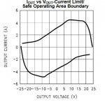
lets think about the figure 11 at the datasheet - attached
the current limit is 4amp up to 20V rail voltage - so with my 27(idle) or 25,3V i am for sure not in the "safe area". with the LM1875 or fake chip
if i calculate the 6R impedance at the TT with 30W i got 5 Amps...so for sure I am in the current limiter.
the temperature at the chip is about 48°C after this "Flamenco"....... is no problem
but now you = experts can explain/help me 😉😀
chris
Attachments
Last edited:
Many thanks Chris for this competent evaluation of a probably fake but dirt cheap amplifier. Even a skilled enthusiast like you find the sound tolerable. It is not because I will now recommend it to anyone with at least some experience in DIY amplifiers. But, my opinion is that young DIYers with a limited budget should make such simple amplifiers for a start because they are very lean on the budget and the result is not ridiculously poor. I guess that also you earned important experience from this your first class AB amplifier.
Also I had such cracking sound from a TDA2050 amplifier (perhaps the same fake chip inside) when I challenged it with heavy bass. Irritating. I believe it could be a flaw in the current limiter.
One day you will also test the genuine LM1875 IC?
Also I had such cracking sound from a TDA2050 amplifier (perhaps the same fake chip inside) when I challenged it with heavy bass. Irritating. I believe it could be a flaw in the current limiter.
One day you will also test the genuine LM1875 IC?
Nice curves. The type of curves that can close the mouth on most while they desperately try to find an explanation. My more simple analysis concludes that the genuine LM1875 has a current limit above 3A (peak) corresponding to 24V in 8 Ohm. Just above what you use it for.
The cracking sound could also be caused by HF self-oscillation as I have seen on my most likely fake LM1875s.
The cracking sound could also be caused by HF self-oscillation as I have seen on my most likely fake LM1875s.
Hi FF
yes yes....since 3 hours listening i can really say this amp is very good and yes everybody should try this. for 2 euros a good mono amp board!!!
yes you are right - the next step is to change the chip to the amazon one = the real recycled....whatever lm1875...remember this chip survived at short cuts🙂
chris
Nice curves. The type of curves that can close the mouth on most while they desperately try to find an explanation. My more simple analysis concludes that the genuine LM1875 has a current limit above 3A (peak) corresponding to 24V in 8 Ohm. Just above what you use it for.
The cracking sound could also be caused by HF self-oscillation as I have seen on my most likely fake LM1875s.
yep...the datasheet says :
Current limiter = at Vsupply -10V ...current limit is 4A...typical 3 A
that means 3App = 2,1 continuous current
i am little bit disappointed that i come so quick into this moment that the current limiter strikes in😀 it was not sooooo loud😀
...hmm... extra transistors?....😉
good night...
chris
Yes, I have some future plans for a mono version with some 6 LM1875. BTL coupling and three in parallel on each side. Buffer transistors is an alternative. A composite structure (error correction) should take the sound to audiophile levels.
Good night.
Good night.
Interesting to see what you get with a genuine LM1875. Mine still has a small pop at turn off which I've never solved.
Yes, I have some future plans for a mono version with some 6 LM1875. BTL coupling and three in parallel on each side. Buffer transistors is an alternative. A composite structure (error correction) should take the sound to audiophile levels.
Good night.
Good morning...FF
this sound like e monster LM1875😎🙂
@rabbitz
will see this weekend...what a genuine chip can/do
chris
other chips....fine sound
Hi
i desolder the fake chip and installed the chips i got from amazon - recycled.
i chip feels at it legs strange-loosy so i be carefully at soldering.maybe they pull it out with too hard mechanic stress. additionally i add at the supply some 100µF caps i got with the kits. the caps which were inside had after lot of hour running an ESR of 0,3R at 100Hz (LCR meter). so with 2 caps in parallel i should achieve the datasheet requirement.
first test i go too fast forward-why? i dont check the DC voltage at the right channel!!! - i am an idiot.....luckly in my lab!
i see during the test with 100mvrms input that i got no signal at the speakers terminals -i checked the rail voltage and see that the -V gets down to 25V and the +V stays at 26,75V. then...🙄...i switched off and see that i had 6,37V DC at the output...chip was F*** hot 😱 and i burned my finger...dead...that chip was the loosy one...
so i changed and every thing stays at 3mV DC on both channels.
i did the shortcut test and both channels survived - so they are original chips --result 3/5 chips are now in my hand from the amazon kits
pop on/off at my lab speaker
no pop on sound - but yes a noticable pop off plop 😱
sound is better and the power is much better. thanks to TI 😀
bass controlled - still not really satisfied (my best is the TPA3255 "fake amp" with...and that new.. 440nF Zobel..at the speakers out....i will report).. separation adn voices come better...and the dynamic (less loud to sme peaks) is much better...but i miss more darkness.....its too foggy in the backround.
i listing now 50 minute and enjoy it...😀
the flamenco title at my listening level was 44 and i can play up to 50 without problems. sorry actually no measurement...today i will enjoy the weather and at the evening i do this task
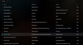
pic is my playlist
chris
Hi
i desolder the fake chip and installed the chips i got from amazon - recycled.
i chip feels at it legs strange-loosy so i be carefully at soldering.maybe they pull it out with too hard mechanic stress. additionally i add at the supply some 100µF caps i got with the kits. the caps which were inside had after lot of hour running an ESR of 0,3R at 100Hz (LCR meter). so with 2 caps in parallel i should achieve the datasheet requirement.
first test i go too fast forward-why? i dont check the DC voltage at the right channel!!! - i am an idiot.....luckly in my lab!
i see during the test with 100mvrms input that i got no signal at the speakers terminals -i checked the rail voltage and see that the -V gets down to 25V and the +V stays at 26,75V. then...🙄...i switched off and see that i had 6,37V DC at the output...chip was F*** hot 😱 and i burned my finger...dead...that chip was the loosy one...
so i changed and every thing stays at 3mV DC on both channels.
i did the shortcut test and both channels survived - so they are original chips --result 3/5 chips are now in my hand from the amazon kits
pop on/off at my lab speaker
no pop on sound - but yes a noticable pop off plop 😱
sound is better and the power is much better. thanks to TI 😀
bass controlled - still not really satisfied (my best is the TPA3255 "fake amp" with...and that new.. 440nF Zobel..at the speakers out....i will report).. separation adn voices come better...and the dynamic (less loud to sme peaks) is much better...but i miss more darkness.....its too foggy in the backround.
i listing now 50 minute and enjoy it...😀
the flamenco title at my listening level was 44 and i can play up to 50 without problems. sorry actually no measurement...today i will enjoy the weather and at the evening i do this task
pic is my playlist
chris
Attachments
...compared to post 184
Hi
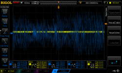
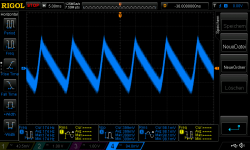
the kit is running some hours and i just checked the "performance" with the "flamenco title" i push 6 time the same track
2 times for the different voltage rails. 3 times for output and once for the input probe.
with the volume level 50 (instead 44). the speakers are 6R (venere1.5)
i cannot explain why i sea at the fake chip at the same title more voltage (38Vpp)at less volume level 44(not 50) now its "just" 35,4Vpp max.--> 26Watt at 6R
the voltage sag down to 25,1V at the heaviest rolls.
no clipping and sound level feels stressed but not at the end...
pic 1 output Rchannel
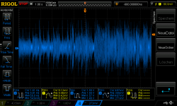
pic 2 input
chris
Hi
the kit is running some hours and i just checked the "performance" with the "flamenco title" i push 6 time the same track
2 times for the different voltage rails. 3 times for output and once for the input probe.
with the volume level 50 (instead 44). the speakers are 6R (venere1.5)
i cannot explain why i sea at the fake chip at the same title more voltage (38Vpp)at less volume level 44(not 50) now its "just" 35,4Vpp max.--> 26Watt at 6R
the voltage sag down to 25,1V at the heaviest rolls.
no clipping and sound level feels stressed but not at the end...
pic 1 output Rchannel
pic 2 input
chris
Attachments
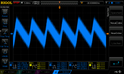
noise at the power supply
Hi
please can you give me ideas to get a better = lower ripple at my power supply. my idea is the get a better sound because of less ripple voltage at the rails
i read about some small caps at the bridge rectifier
and what about bleeder resistors at the cap bank or some foil caps?
amp on, complete connected but no signal
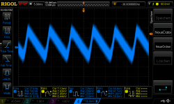
pic 1 ripple at the +V and -V after the rectifier
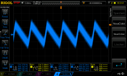
pic 2 ripple at the L channel +V and 0 at the cap bank
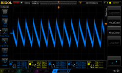
pic 3 ripple at the L channel -V and 0 at the cap bank
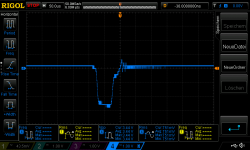
pic 4 L channel off pop 😱
thanks in advance
chris
Hi
please can you give me ideas to get a better = lower ripple at my power supply. my idea is the get a better sound because of less ripple voltage at the rails
i read about some small caps at the bridge rectifier
and what about bleeder resistors at the cap bank or some foil caps?
amp on, complete connected but no signal
pic 1 ripple at the +V and -V after the rectifier
pic 2 ripple at the L channel +V and 0 at the cap bank
pic 3 ripple at the L channel -V and 0 at the cap bank
pic 4 L channel off pop 😱
thanks in advance
chris
Attachments
i did my reporting- fyi.........
sound is better and the power is much better. thanks to TI 😀
bass controlled - still not really satisfied (my best is the TPA3255 "fake amp" with...and that new.. 440nF Zobel..at the speakers out....i will report).. separation adn voices come better...and the dynamic (less loud to sme peaks) is much better...but i miss more darkness.....its too foggy in the backround.
i listing now 50 minute and enjoy it...😀..
chris
https://www.diyaudio.com/forums/class-d/309813-wrong-tpa3255-92.html#post5943118
chris
Hi
please can you give me ideas to get a better = lower ripple at my power supply. my idea is the get a better sound because of less ripple voltage at the rails
i read about some small caps at the bridge rectifier
and what about bleeder resistors at the cap bank or some foil caps?
amp on, complete connected but no signal
pic 1 ripple at the +V and -V after the rectifier
pic 2 ripple at the L channel +V and 0 at the cap bank
pic 3 ripple at the L channel -V and 0 at the cap bank
pic 4 L channel off pop 😱
thanks in advance
chris
Hi Chris,
A typical ripple-form for a non-regulated power supply. If you double the decoupling capacitance, you will have close to half the ripple but you can't just increase the capacitance without getting space problems and too much invested in capacitors.
It is a 100Hz ripple of a moderate amplitude. In-between recharge of the capacitors every 10ms, the capacitors provide the current and are discharged as you see. The curve is a bit blurred but with a sampling scope and high gain, my experience is that a blurred picture can be expected.
Rectifier capacitors and foil capacitors will only have a small effect on higher frequency ripple. Bleeder resistors serve to give a slight minimum-loading (which you already have from quiescent current) and more importantly quickly remove charge from the decoupling capacitors when you switch the amplifier off.
What to do then? Use regulators on the two rails. Then, you have considerably less ripple but only audiophiles like you can evaluate the improvement of the sound. Several volts of ripple can be an important issue, not your modest level.
Last edited:
Good Evening FF
greetings from the foggy Vienna .🙁
Thanks for your feedback. yes every 10ms the caps get juice. with my 2x2200+2x1000µ (6400) per rail for both amp boards i am not in the correct window.
10000µF are required per rail and amp. correct?.....and yes the space is not really big in my housing / or mock up😉
i will try to get some extra caps in my mock up.....
i have no bleeder resistor maybe this is the reason why i have a off pop.
so far i am still happy with the sound of the original LM1875. the power is just fine. sound wise the background is still foggy - means its a lack of dynamic especially from the background + the bass is still bloated
chris
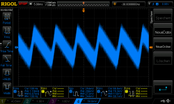
Hi
i did a small modification in the morning on my bridged rectifier- a solder a 22nF ceramic caps at all pin (diodes) + i add a 220nF /250 X2 caps after the rectifier at +V and -V.
the results is not better...soundwise the same....should i pull that out?
amp on, complete connected but no signal
pic 1 ripple at the +V and -V after the rectifier
pic 2 ripple at the L channel +V and 0 at the cap bank
pic 3 ripple at the L channel -V and 0 at the cap bank
chris
Attachments
Hi
i did a small modification in the morning on my bridged rectifier- a solder a 22nF ceramic caps at all pin (diodes) + i add a 220nF /250 X2 caps after the rectifier at +V and -V.
the results is not better...soundwise the same....should i pull that out?
amp on, complete connected but no signal
pic 1 ripple at the +V and -V after the rectifier
pic 2 ripple at the L channel +V and 0 at the cap bank
pic 3 ripple at the L channel -V and 0 at the cap bank
chris
Hi Chris,
The small capacitors on the rectifier diodes may help the diodes switching off but they hardly change the sound. I never used such capacitors myself so I will let more competent people advise on "stay, or go".
10000uF is not a magical value. Theoretically - the more, the better. With the moderate prices for 10000uF, my advice is not to use too little or even some of more ordinary quality.
The off pop comes from when the amplifier gets starved for voltage during switch-off and looses regulation control. The bleeder resistors may not help on that. In the old days, a safety relay disconnected the speakers before the amplifier lost control.
NB: Always switch off the power amplifier before the pre-amplifier and source. Else, the pop comes via the input.
Sun and 27 degrees today. But, Atlantic air is approaching.
Last edited:
- Home
- Amplifiers
- Chip Amps
- eBay mono LM1875 kit