Sorry, during the many changes, I lost the track of the original circuit.
Now things look better, but the saturation effect remains present, albeit at a smaller level.
Nothing of the sort appears in your real world oscillograms, and Tom didn't mention anything about this either, meaning it is a model-induced artifact.
This means that any optimization for this aspect would need to rely on reality (or better models)
Attachments
Here is the point I wanted to illustrate: the detrimental effect of the gate-stopper.
These sims have to be taken for what they are worth, that is little in absolute terms, because the darlington does not quite behave like the real thing, but their relative aspect is probably more valuable.
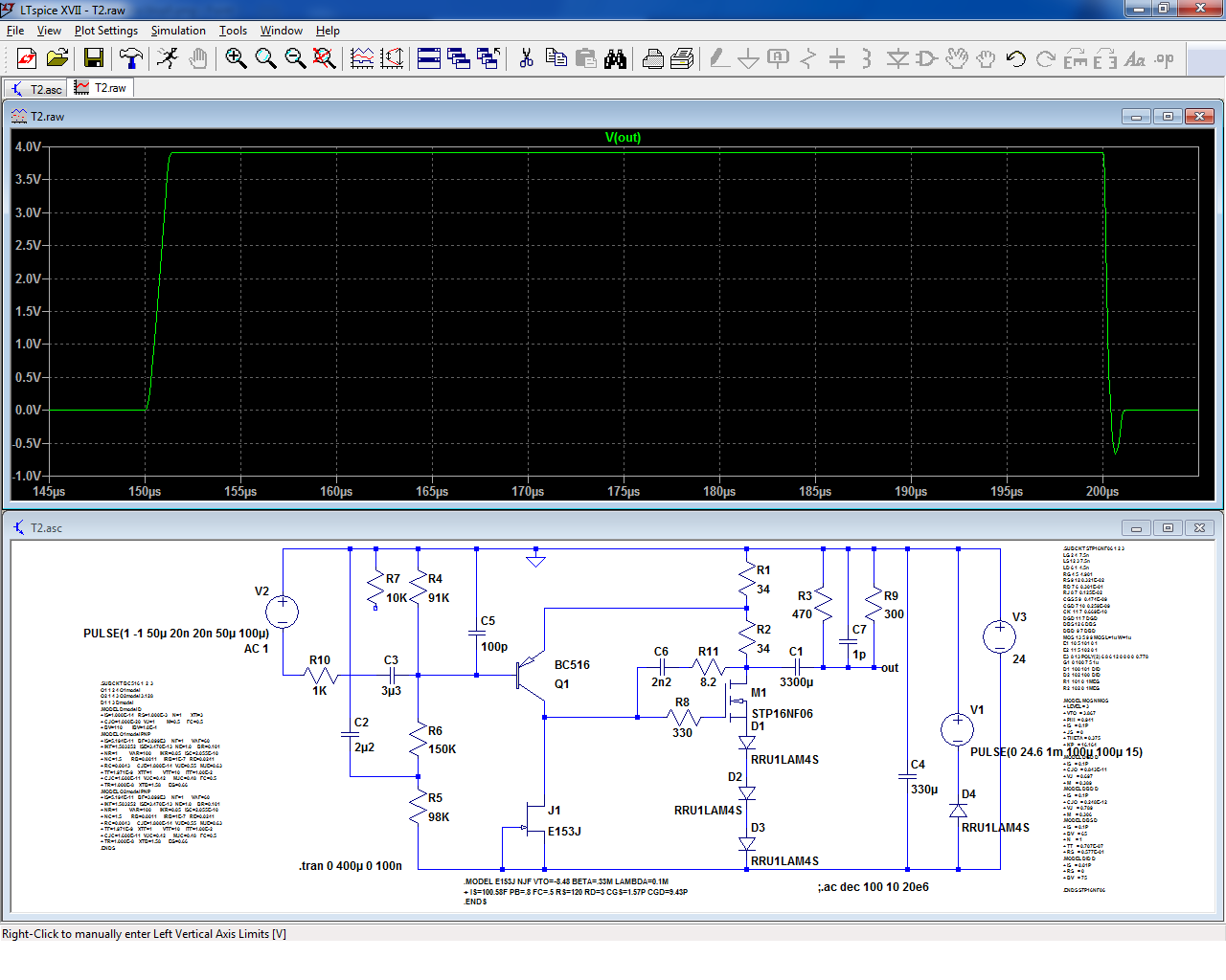
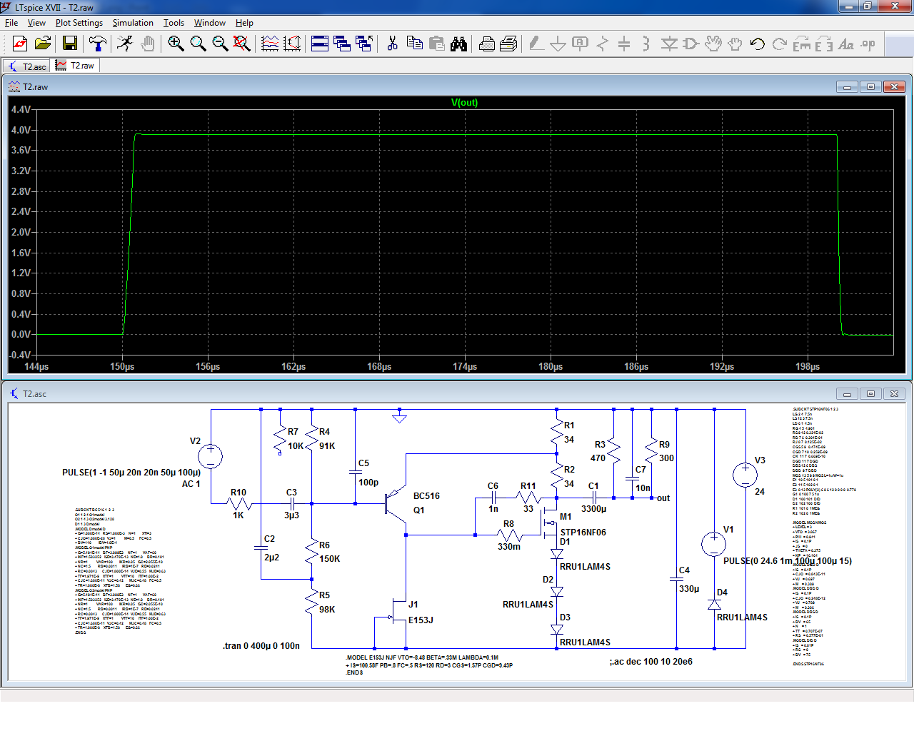
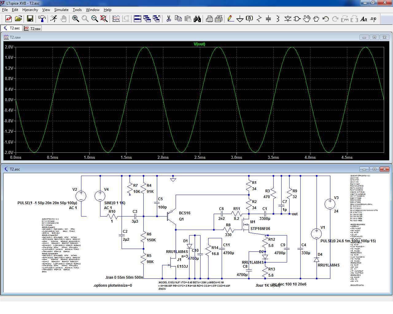
Hoping I didn't mess or forget something this time, here is the response with the original values and a purely resistive load:
Now, the gate-stopper is removed, and the compensation components are adapted to take advantage of the improved phase margin:
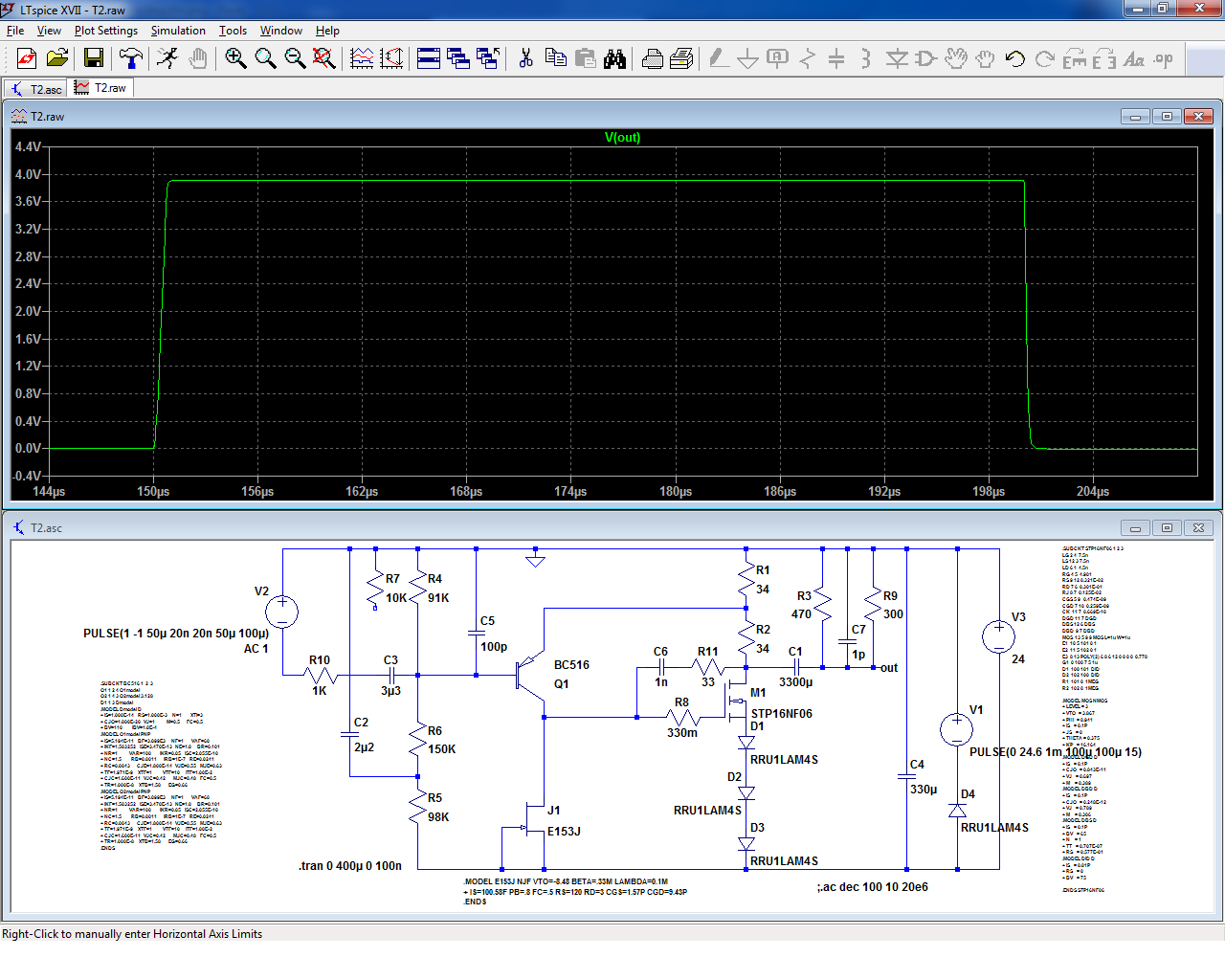
Here is the response of the original with 10nF of capacitive load; no ringing is visible which is an anomaly, but the undershoot has increased:
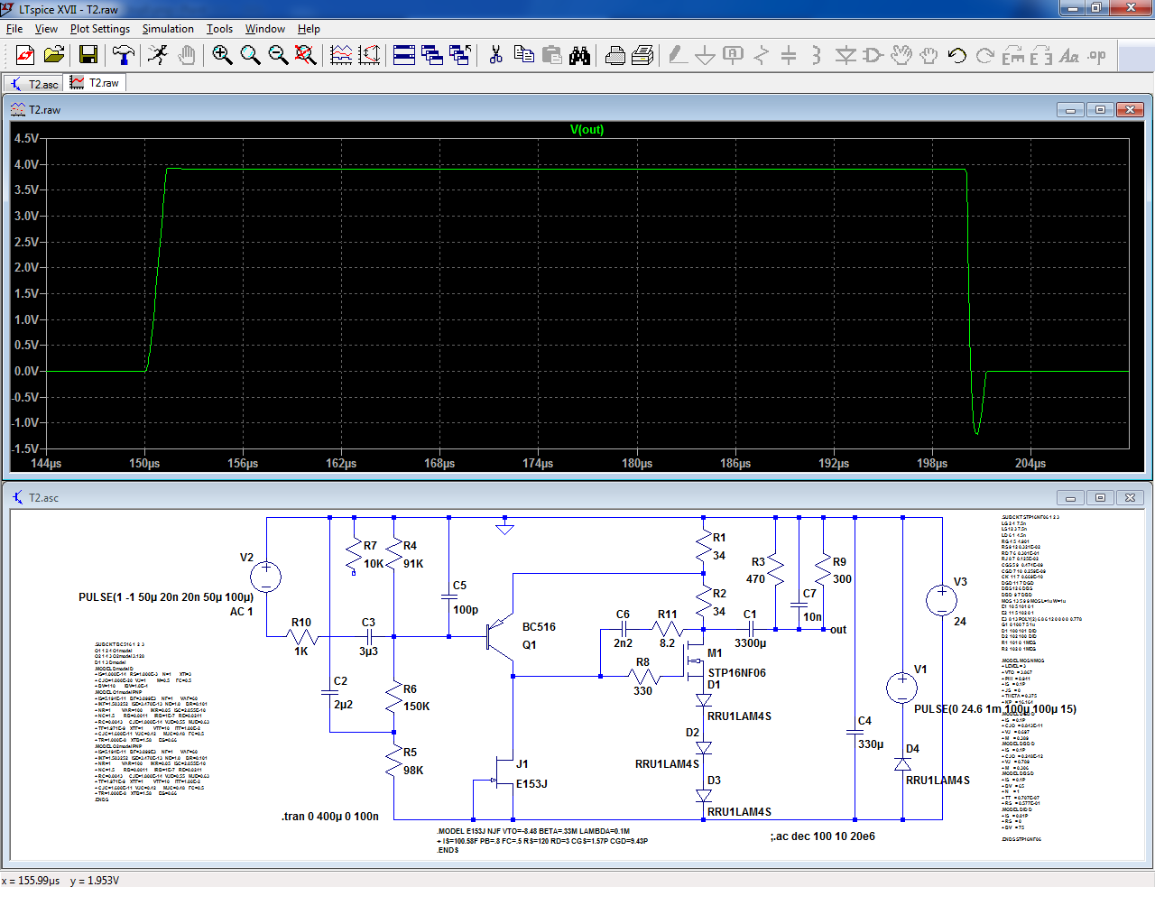
Now the same without the gate-stopper:
I wouldn't rely too much on the exactitude of these results when translated in the real world, but both the AC analysis and the transient response convey the same message: the gate-stopper does harm.
Thus, if it is possible to dispense with it, improvements will be gained.
As I said, I see the ringing as a minor issue unlikely to much cause harm, but if it can be ironed-out easily and cheaply it would be silly to miss the opportunity.
To summarize: in order to address the main issues raised by Tom, the mods to be carried out (by order of importance) are:
-Use a multipole power switch also disconnecting the output
-Increase the bias bypass caps to 47~100µF
-Replace the gate stopper by a 1 ohm resistor, and optionally adapt the compensation network (this has has to be tested in reality to determine the optimal values -the sim cannot be relied upon-)
Note that the effect of the three mods has to be verified in reality: that is particularly true for the gate-stopper, as it could result in unwanted oscillations.
If all goes well, the main identified issues will be eliminated, at a minimal cost and without having to rework the PCB: just some minor component swapping required.
These sims have to be taken for what they are worth, that is little in absolute terms, because the darlington does not quite behave like the real thing, but their relative aspect is probably more valuable.
Hoping I didn't mess or forget something this time, here is the response with the original values and a purely resistive load:
Now, the gate-stopper is removed, and the compensation components are adapted to take advantage of the improved phase margin:
Here is the response of the original with 10nF of capacitive load; no ringing is visible which is an anomaly, but the undershoot has increased:
Now the same without the gate-stopper:
I wouldn't rely too much on the exactitude of these results when translated in the real world, but both the AC analysis and the transient response convey the same message: the gate-stopper does harm.
Thus, if it is possible to dispense with it, improvements will be gained.
As I said, I see the ringing as a minor issue unlikely to much cause harm, but if it can be ironed-out easily and cheaply it would be silly to miss the opportunity.
To summarize: in order to address the main issues raised by Tom, the mods to be carried out (by order of importance) are:
-Use a multipole power switch also disconnecting the output
-Increase the bias bypass caps to 47~100µF
-Replace the gate stopper by a 1 ohm resistor, and optionally adapt the compensation network (this has has to be tested in reality to determine the optimal values -the sim cannot be relied upon-)
Note that the effect of the three mods has to be verified in reality: that is particularly true for the gate-stopper, as it could result in unwanted oscillations.
If all goes well, the main identified issues will be eliminated, at a minimal cost and without having to rework the PCB: just some minor component swapping required.
Attachments

Would someone draw up a new schematic with these (3) solutions incorporated?
It would help me in the translation between the simulation drawings and the actual circuit.
Also possibly updating the 6L6 build guide to include these "improvements" ?
Many Thanks
Alex
It would help me in the translation between the simulation drawings and the actual circuit.
Also possibly updating the 6L6 build guide to include these "improvements" ?
Many Thanks
Alex
Elvee, you may want to resort to the models and symbols posted earlier in this thread (some time in late July, I think). I'm seeing nothing out of the ordinary at 10 nF, and 22 nF is about the limit of stability. It is true, however, that reducing the gate stopper enables better capacitive driving and higher GBW. With the values given it'll get to about 82 nF. Either is fine though.
Incidentally, I've played with adding a bootstrapped cascode to the input, along the lines of what I used in my 3-transistor preamp. Seems to work OK if you also add a bit of input bootstrapping, and will cope with silly amounts of Darlington input capacitance like 100 nF (not recommended - frequency response will stay up but distortion will suffer as gain is expended for the bootstrapping). May post schematic later but right now it looks messy.
Incidentally, I've played with adding a bootstrapped cascode to the input, along the lines of what I used in my 3-transistor preamp. Seems to work OK if you also add a bit of input bootstrapping, and will cope with silly amounts of Darlington input capacitance like 100 nF (not recommended - frequency response will stay up but distortion will suffer as gain is expended for the bootstrapping). May post schematic later but right now it looks messy.
Yes, these are the ones I used.Elvee, you may want to resort to the models and symbols posted earlier in this thread (some time in late July, I think).
The issues I have with these models, the BC in particular, is that they don't reproduce the behavior observed on resistive load (by Mark) and on capacitive load (by Tom).
Instead, there is a single undershoot event at the negative transition, which I traced to the saturation of the BC lasting well after the transition (in sim at least).
Since nothing of the sort appears in reality, there has to be something wrong with the models, like carriers life time
In real life, there is a fair amount of ringing with 10nF (hidden in sim by the saturation).I'm seeing nothing out of the ordinary at 10 nF,
As I said earlier, nothing really problematic or catastrophic, but since the gate-stopper seems to play a major role in that, eliminating it (if layout permits) would be a good (and totally free) improvement.
Gaining stability, especially for free, is always worthwhile.
I am always interested in creative schemes (and I am certainly not alone), especially those that push the envelope far beyond the normality.Incidentally, I've played with adding a bootstrapped cascode to the input, along the lines of what I used in my 3-transistor preamp. Seems to work OK if you also add a bit of input bootstrapping, and will cope with silly amounts of Darlington input capacitance like 100 nF (not recommended - frequency response will stay up but distortion will suffer as gain is expended for the bootstrapping). May post schematic later but right now it looks messy.
Maybe you could start a new thread when you are ready (with just a link here), to avoid cluttering Mark's subject with topics that are not directly relevant to his amplifier.

It could make a fraction of a dB difference here and there at most, but if you find it improves matters, good for you.... that's DIY!Bypass the diodes...
It is probably a good opportunity to remind everyone of what DIY is really about: tinkering, playing with non-optimal topologies and technologies, and sharing the results.
One shouldn't apply the same "quality" standards to a cheap, commercial product and something special, like a tube amplifier, Pass amplifiers or the T2.
We could as well close these sections of the forum, since what is proposed is not up to spec, compared for example to cheap Asiatic products (and don't be mistaken: I don't dismiss cheap Asiatic products: they show a good deal of creativity and effectiveness for a minimal cost, which is a remarkable performance).
What I mean is that Mark could simply have stacked some Hiperf opamp from TI and Hiperf buffer from ADI (just examples), and gotten a much higher perf HP amp, but that's something about anybody reasonably competent could do, so what's the interest?
Just buy the Asian kit, and that's it.
The T2 has just two active elementary semi's (OK, maybe 2.5), so what do you expect?
Just ultra-fine specs?
That would be unreasonable: you want something decent enough but with a character of its own. Otherwise, just buy cheap, standard (boring), high-perf stuff.
The T2 fulfills these goals; it has (had?) one or two annoying quirks, but you can live with it or correct them.
Otherwise, it is a quite decent amplifier with its peculiarities, but you cannot realistically apply the same objective quality standards to an amp like the T2 and a modern, integrated amp.
To take a car example, try to compare a Jaguar E-type and any modern car, and I am not only talking of top notch Porsche, Ferrari or Mercedes: almost any >1500cc modern car would outperform an E-type on road, but that's not what the competition is about.
I am a great fan of objective measurements, because they provide a reference, and a basis for improvement, but there are cases where they are just informative
Simulation predicts about 13 dB less distortion due to correspondingly increased loop gain... nothing to sneeze at IMHO, especially for just one extra component. Of course that's assuming that actual dynamic impedance is close to what the 1N4004 model says it is, but I mean, assuming you bothered to model a diode, getting Vf(I) about right would be among the most basic things to do, don't you think?It could make a fraction of a dB difference here and there at most, but if you find it improves matters, good for you.... that's DIY!
I got the 3PDT switch today and installed, the turn off thump is gone! Yeah!
Question for the 68 uf cap for the turn of thump would a non polarized cap work or is a electrolytic really needed??
Ex: 68uF 100V Electrolytic Non-Polarized Crossover Capacitor
Alex
Question for the 68 uf cap for the turn of thump would a non polarized cap work or is a electrolytic really needed??
Ex: 68uF 100V Electrolytic Non-Polarized Crossover Capacitor
Alex
Simulation predicts about 13 dB less distortion due to correspondingly increased loop gain... nothing to sneeze at IMHO, especially for just one extra component.
Very smart observation indeed: I get practically 20dB improvement!
I had analyzed the circuit at a glance, making simple mental calculations and had (wrongly) concluded that with a dynamic resistance of ~26/150=0.17, the effect was going to be marginal, but actual diodes have a somewhat larger resistance at high currents, and they also add non-linearities of their own, so the cap is in fact very useful, and pushes the amplifier into a different league!
In theory, if you bypass diodes to GND, you would get turn-on/off transient reduction as well.
At least, this works for negative-gnd circuits. Perhaps positive-gnd has a wholly different mojo!
At least, this works for negative-gnd circuits. Perhaps positive-gnd has a wholly different mojo!
Is there any consensus as to what size capacitor we should look to bias the diodes with?
(Single ended class-A headphone amp using two transistors: T2)
It looks like Alex used 4700uF 16v there, but I used 3300uF 10v and was warned to carefully select the value or it will affect the LF response.
(Single ended class-A headphone amp using two transistors: T2)
It looks like Alex used 4700uF 16v there, but I used 3300uF 10v and was warned to carefully select the value or it will affect the LF response.
If you're not careful when choosing the capacitor value, you can accidentally put the corner frequency in the (audible) high bass region. Which will ruin the response in the low bass. Draw it up on the chalkboard and write some equations.
With the bypass cap, the diode string is not necessary anymore: it can be replaced by a single ~17 ohm resistor.
Incidentally, it will also improve the DC stability.
One could go overboard and replace the whole string with an error-correcting one:
It brings another three-fold THD reduction on top of the ~20dB already packed!
Incidentally, it will also improve the DC stability.
One could go overboard and replace the whole string with an error-correcting one:
It brings another three-fold THD reduction on top of the ~20dB already packed!
Attachments
Toggle Switch, 3PDT, ordered (slow boat from china).
Always fun to arrive home after work and find a mysterious package has arrived that you cant remember the contents of or ordering as its been so long. lol
Always fun to arrive home after work and find a mysterious package has arrived that you cant remember the contents of or ordering as its been so long. lol
Member
Joined 2009
Paid Member
ha! I actually had a good idea, first time in 55 years 😀
I got the 3PDT switch today and installed, the turn off thump is gone! Yeah!
Alex
55 years! Ha Cool!
OBTW...I did use a 4700uf cap to bypass the diodes and dont hear any real bass reduction?
Still would like an opinion on using a non polorized electrolytic for the bypass "remove" the turn on thump solution?
Also with the bypass caps in place the turn on and turn off thump is still there in spades!
The switch works nicely for the tunr off and I used the one Mark linked to in the thread...thanks Mark, for some reason I looked and looked
and did not see the 3T switches (duh!)...
Alex
Last edited:
One simple workaround here for the turn on thump is turn on the amp, wait about a minute then plug in your headphones in, no thumps!
Almost as good as the Nelson Pass solution of leaving it on all the time!
LOL
Alex
Almost as good as the Nelson Pass solution of leaving it on all the time!
LOL
Alex
- Status
- Not open for further replies.
- Home
- Amplifiers
- Headphone Systems
- Single ended class-A headphone amp using two transistors: T2