Isn't it about time for some regurgitation of old ideas? Better to have a nap.......
Sorry, I'm fresh out of old ideas.
I have a pair of Selenium D205TI replacement coils, 2 inch diameter kapton vc former, titanium dome..
I am cutting some OD shorting rings to try. 20 mils clearance to wires, in aluminum, brass, copper, and a steel to be named later. All are 100 mils thick, OD of rings will be 2.6 inches give or take.
Calculate intrinsic inductance of the non magnetics (won't know the mu of the iron), the resistance of the loops, and the simple LR break frequency.
Tests will be 20hz to 100 Khz.
Ls/Rs.:
Bare coil
copper
brass
aluminum
magnetic steel
Then, cut all rings with a jewelers saw, measure the actual ring inductances, and repeat the four shorting ring tests with broken conductivity.
then work on making a full iron magnetic path with solid iron everywhere...
Measure Ls/Rs in full iron circuit.
Isolate faceplate from back using 1 or 2 mil nomex, repeat Ls/Rs
cut faceplate slit, repeat Ls/Rs.
Have the brass and aluminum almost fully turned. I've seen on a clock making website how he used superglue to hold thin parts on a faced mandrel, this will be my first time trying that.
Honestly, I don't know if I enjoy the machining learning curve or the electrical testing more...
Ah, I've decided on using the non expanding foam to make my cone clamp. I fear the expanding foam.
jn
JN, I did a bit of looking to get up to speed of what you are researching and came up with these - Push-pull versus shorting rings and JBL Magnet structures.
A bit more searching and sleuthing came up with these papers which may be of help - View attachment FaradayRingsVoiceCoilImpedance.pdf and View attachment 700SeriesWhitepaper.pdf
It seems the first thing to implement is T section centre pole piece and then flux disc on top of polepiece and aluminium ring at the base of the centre pole piece.
Cheers, Dan.
What's the word to describe the one who pontificates and then complains about hacklers?I like the idea of "giving someone a hard time" when they are pontificating.
Thank you. I didn't have the B&W 700 whitepaper. The audioroundtable stuff, man, wayne parnham, a name from the past.JN, I did a bit of looking to get up to speed of what you are researching and came up with these <snip>
The Amhet paper I found about a week ago.
Again, thanks.
John
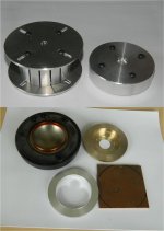
Edit..update on the winding mandrel and tweeter rings...
Made two side plates for the mandrel, slotted so they allow the mandrel to expand. The M3 screws are tightened after mandrel is sized. The fixture on the right was used to make the plates.
The second pic is an old blown tweet coil (my son), then brass, alum, and copper blank. Haven't purchased any magnetic steel yet.
Attachments
Last edited:
I found the B&W 700 paper in Wayback Machine - https://web.archive.org/web/2006031...File/technicalFeature/700SeriesWhitepaper.pdf
Maybe this search method is help to you to find other 'lost' papers and books.
Dan.
Maybe this search method is help to you to find other 'lost' papers and books.
Dan.
What's the word to describe the one who pontificates and then complains about hacklers?
I've no idea, perhaps a word needs to be invented. They tend to be self proclaimed "golden eared" audiophiles who are also in the business of using this site to peddle their wares, and not in commercial forums. One of the worst offenders is a moderator who is not above abusing his power here to remove posts and threaten members that ask questions that don't fit his agenda, and change thread titles to potentially boost his business.
Evidence ?...... One of the worst offenders is a moderator who is not above abusing his power here to remove posts and threaten members that ask questions that don't fit his agenda, and change thread titles to potentially boost his business.
Dan.
Privacy is what that is.
The hell with privacy. We need your personal details so we can harass you!
using a website calculator for solenoid inductance and metal resistance..
Copper shorting ring....
L =.1 uH
R = .343 mH
Break frequency 546 hz
Aluminum shorting ring
L = .1 uH
R = .543 mH
Break frequency 864 hz.
jn
Copper shorting ring....
L =.1 uH
R = .343 mH
Break frequency 546 hz
Aluminum shorting ring
L = .1 uH
R = .543 mH
Break frequency 864 hz.
jn
I like the idea of "giving someone a hard time" when they are pontificating.
Scott Wurcer had the best one I've ever heard on that issue
'Leave no guru unstoned'
hilarious!
What's the word to describe the one who pontificates and then complains about hacklers?
drama queen i.e. pontificatory self-victimisation
I recall (just barely) during my drinking daze being at a bar with a friend and we were yelling out comments at the band (we were all friends) when all of a sudden the bar owner yelled out:
"No professional heckling!"
"No professional heckling!"
Just about anything is patentable (though it helps to have a patent attorney put it into the right language), as long as the patent application doesn't include the phrase "perpetual motion machine."That's probably patentable..😎
Jn
They just about don't make JFETs anymore. I'm even surprised they still make followers.Like JFET follower 😉
What, has the topic turned to mathematics?I presume you mean proof?
Just to let people know, my Erdos Number is infinity, and that's not likely to change. It'll certainly not get down to 1.
Indeed a lot of fishy activities is going on, here. Under cover, sneaky marketing.I've no idea, perhaps a word needs to be invented. They tend to be self proclaimed "golden eared" audiophiles who are also in the business of using this site to peddle their wares, and not in commercial forum.
As to a front plate being a single turn short, that's been around what, 100 years? Has it been questioned before? If not, shouldn't it be?
From US Patent 5715324
Speaker having magnetic circuit
ALPINE ELECTRONICS INC
FIG. 7 is a section view of a conventional speaker. ....
In the aforementioned conventional speaker, the ring-shaped iron plate 73 and the iron yoke 77 are used as component parts of the magnetic circuit. Therefore, the magnetic field of the voice coil 76 produced by applying voice current (alternating current) thereto develops eddy currents in the ring-shaped plate 73 and the yoke 77 which define the magnetic gap 79. These eddy currents are the primary cause of sound distortion.
The very low inductance of the voice coil 76 increases to a high value when it is placed close to the ring-shaped iron plate 73 and the iron yoke 77. Therefore, the impedance increases from the intermediate-frequency to high-frequency ranges, which leads to reduced sound conversion efficiency. At the same time, phase rotation increases due to impedance, which causes a distortion in the output sound phase.
5715324
Attachments
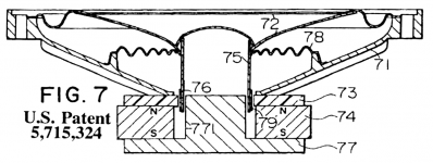
So it's clearly mentioned as a problem. I searched the patent, but didn't notice a radial slit in the front plate. Was it there? I must admit, I had a hard time going through it.😱
jn
jn
- Status
- Not open for further replies.
- Home
- Member Areas
- The Lounge
- John Curl's Blowtorch preamplifier part III