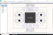
Complete Schematic
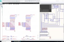
Here is the complete schematic with both connectors.
Here, PSN and TEST will have to be hardwired on the board.
Tomorrow, I'll work on MCLK.
Here is the complete schematic with both connectors.
Here, PSN and TEST will have to be hardwired on the board.
Tomorrow, I'll work on MCLK.
Attachments
Last edited:
Headphone Preamps
A friend of mine suggested two alternative preamps for the Audeze LCD-X:
Burson HA-160D
Shiit Jotunheim
I will listen to both of them next week in a shop that carries them in Tokyo.
A friend of mine suggested two alternative preamps for the Audeze LCD-X:
Burson HA-160D
Shiit Jotunheim
I will listen to both of them next week in a shop that carries them in Tokyo.
I will listen to both of them next week in a shop that carries them in Tokyo.
How will you compare them to Massdrop?
How about comparing to Benchmark HPA4?
How will you decide which is better?
EDIT: A friendly word, if I may be candid: IMHO, your friend has given you audiophool advice. Your money though.
Probably best to go with Benchmark and forget the others, you won't be sorry. You just might end up with one in the end no matter which others you buy first. Hard lesson to learn for some. Jam has some hilarious 'I told you so,' stories about some other types of audio gear.
Last edited:
How will you compare them to Massdrop?
How about comparing to Benchmark HPA4?
How will you decide which is better?
EDIT: A friendly word, if I may be candid: IMHO, your friend has given you audiophool advice. Your money though.
Probably best to go with Benchmark and forget the others, you won't be sorry. You just might end up with one in the end no matter which others you buy first. Hard lesson to learn for some. Jam has some hilarious 'I told you so,' stories about some other types of audio gear.
I will try to listen to all three (including the Massdrop) using the same tracks and the same headphones. I will buy an affordable one first ($400), before upgrading to a more expensive one.
I will try to listen to all three (including the Massdrop) using the same tracks and the same headphones.
Same DAC?
Reason I ask is the HPAs your friend recommends are good for masking the distortion of cheap DACs by using their own distortion to reshape the overall distortion, IME with similar user equipment choices. IMHO, the distortion specs on the Burson dac aren't very good, and the higher priced Schiit units feature vacuum tubes sticking out the top (that says it all, some people like a little tube distortion).
Last edited:
Which one?
I do not know. I will do my best to try different ones at the listening studio(s).
No Hardwired Pins
The AKM evaluation board does not hardwire pins like TEST (56), and I am a bit concerned that we might regret the decision of hardwiring PSN (41) as well. Therefore, we've added both to the J6 ERM8 connector. This cost us two ground return signal, yet every single digital circuit pin keeps an adjacent ground return signal pin, so we should be fine.
Better safe than sorry...
Attachments
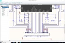
Updated Schematic
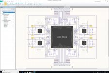
Here is an updated schematic with fixes for all known errors. It compiles with no errors.
The next step is to quickly lay out a first PCB, just to see how much space we have left for additional components like the clock and some LDOs, and whether everything will fit within a 2 × 1 brick, or whether we have to go to a 3 × 1 layout. My hunch is that 2 × 1 will be tight, and 3 × 1 should leave us plenty of space for some on-board LDOs. The latter option is probably best, but we'll start with a 2 × 1 layout just to force ourselves to keep things as tight as they can be in a first iteration.
Attachments
Kit #8
Kit #8 is heading to Portland, Oregon.
By the way, all kit numbers have been shifted by one position, because I forgot that kit #1 was reserved for the original initiator of the project (a French audiophile who introduced me to the concept of clock jitter a few years back).
Only 4 kits left now...
Kit #8 is heading to Portland, Oregon.
By the way, all kit numbers have been shifted by one position, because I forgot that kit #1 was reserved for the original initiator of the project (a French audiophile who introduced me to the concept of clock jitter a few years back).
Only 4 kits left now...
I just became aware of this project (#8) and am just getting all the thread read.
But I haven't seen the question of multiple outputs vs mono addressed. I looked at the AKM sheet and was initially surprised to see the mono mode was voltage summing vs current summing before conversion as that is the methodology I am familiar with. I'm sure there are reasons to do that with this chip, that is for the manu to spec. But it does allow for an easy conversion on the back side to implement, especially in the way it is being conceived with the xlr board, where addition can occur. But, are there other concerns that need to be allowed for in the pin assignment and feeding?
Like I said, I still need to catch up on the reading, about half way there.
Cheers
Alan
Last edited:
I just became aware of this project (#8) and am just getting all the thread read.
But I haven't seen the question of multiple outputs vs mono addressed. I looked at the AKM sheet and was initially surprised to see the mono mode was voltage summing vs current summing before conversion as that is the methodology I am familiar with. I'm sure there are reasons to do that with this chip, that is for the manu to spec. But it does allow for an easy conversion on the back side to implement, especially in the way it is being conceived with the xlr board, where addition can occur. But, are there other concerns that need to be allowed for in the pin assignment and feeding?
Like I said, I still need to catch up on the reading, about half way there.
Cheers
Alan
Currently, the thinking is that the core DAC board (the one for which we now have a full schematic) will be independent of that. In other words, you could use the same DAC board in 4-channel mode, in stereo mode, or in mono mode. All that will be required is different XLR boards. These will be really simple, and we'll provide schematics for all three. And the kits will come with all three boards so that comparative tests can be performed relatively easily.
Nets Containing Multiple Similar Objects
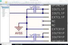
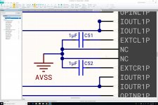
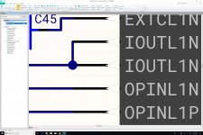
This one is for the Altium Designer/CircuitStudio experts: the attached schematic generates the following PCB compilation error:
Nets Containing Multiple Similar Objects
It is described on this article.
I'm sure that I could get rid of the error by changing the pin type for the two IOUTL1N pins, but I'd like to avoid that. Any other way to work around the problem?
Or should I just edit the Connection Matrix? I don't really like this kind of hardcore solution either because it defeats the purpose of using proper pin types, but I can't think of anything else.
Attachments
Last edited:
You should hardwire PSN. You will never want or be able to run the dac in pin control mode anyway. You don't have near enough connectors for all the dual-use pins, for starters. And what the dac can playback in pin control mode is very limited.
By the way, be sure any headphone amp you consider has both balanced and single-ended analog inputs 🙂
You should hardwire PSN. You will never want or be able to run the dac in pin control mode anyway. You don't have near enough connectors for all the dual-use pins, for starters. And what the dac can playback in pin control mode is very limited.
I think I'm starting to understand what you're saying. It might take a while for it to sink in though...
- Home
- Source & Line
- Digital Line Level
- 8 × AK5578EN + 8 × AK4499EQ ADC/DAC Boards