If the collector load is also changed, the base 180K should of course be scaled ~accordingly (and also the cap values)
Does the 180k matter , because the hfe of different transistors can go from 100 to 400 or more. BC337 goes from 160 to 600 depending on -25 or -40 version. ZTX 100-200.
Which cap values should be changed ?
Yeah , it is a bit weird that Elektor put 10 ohm at the LM's output . Since it is a slow rise start , the big 4700uF shouldn't be a problem at power up.
"I doubt you could hear any rattling directly" .
Well I did hear some very faint rattling , but it was gone after the CRC so now I'm not sure if I'm going to use the 22nF I already bought to put over the diodes. I use ultra fast diodes , just because I can and they're cheap.
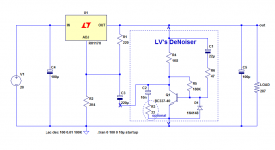
Here's one from Elektor 86 's preamp, I think . Notice the big 4700uF cap after the LM. I could be wrong but I still trust Elektor more than some on a forum.
I won't dismiss your observation out of hand...I have the equipment here and a variety of diodes from 1N4002, 1N4007, UF4007, MBR's etc., even some germaniums and selenium rectifiers.
The picture which I posted of the ringing diode is from an experiment with a transformer salvaged from a Hewlett Packard amplifier -- high leakage inductance.
Don't want to cloud up Elvee's thread so will start afresh when I have some data. Stay tuned.
The circuit is designed for highish Hfe transistors, like the BC337-40 or the ZTX.Does the 180k matter , because the hfe of different transistors can go from 100 to 400 or more. BC337 goes from 160 to 600 depending on -25 or -40 version. ZTX 100-200.
However, because of the (feedback) mode of bias, and the fact that the correction amplifier should only operate on a small dynamic range*, practically any gain range will always work with any bias resistor (within reason, of course).
What is going to change is the performance: I have used a collector resistor as large as possible, whilst keeping the collector current as large as possible, to maximise the transconductance and the voltage gain.
Since these objectives are somewhat contradictory, the C-E voltage is kept to the minimum practical to remain in the fully linear range, and accept normal component deviations.
If you go outside the normal deviation, the circuit will continue to function, but with a penalty of perhaps 2~3dB, depending on the values.
*
I have made a stress test on the nonoiser (see some posts above), and when the ripple reaches insane values, the correction amplifier begins to saturate and do weird things.
Since the denoiser operates on the same principle, it is probably also subject to the same kind of "trouble".
I say "trouble" with quotes, because in a low level, audio oriented regulator, the ripple is going to be LF, and its proportion will be in the low % range at most, not 100%
Both the input and output caps: if you increase the collector load, you have to increase the bias resistor in the same proportion, and decrease the cap values, again in the same proportion (you can keep them identical, and it will benefit the VVLF rejection, but increase the startup time)Which cap values should be changed ?
I am certainly not dismissing the observation either, and what happens on the AC side can be pretty horrendous, as your oscillograms show, but I am trying to interpret what "rattling" could mean: for me, it would be a non-completely harmonically-related noise, like a loose mechanical part periodically excited by something.I won't dismiss your observation out of hand...I have the equipment here and a variety of diodes from 1N4002, 1N4007, UF4007, MBR's etc., even some germaniums and selenium rectifiers.
Rick might have a different idea, and for him, certain harmonics could sound like rattling.
What happens in common-mode, or in differential mode upstream of the diodes is normally going to be hugely attenuated by the reservoir cap which will normally have an ESR <100mΩ.
To pass something like what I call rattling, the diodes would need to conduct several times again during the ringing (rattling) period, to inject significant current spikes into the cap.
That is a behavior I have observed, but in different circumstances: in SMPS, when a snubber diode is extremely slow (which can have advantages), it appears, but the rattling frequency is then related with the Trr of the diode, which rarely exceeds 10µs, which is normally too short to produce audible effects
Both the input and output caps: if you increase the collector load, you have to increase the bias resistor in the same proportion, and decrease the cap values, again in the same proportion (you can keep them identical, and it will benefit the VVLF rejection, but increase the startup time)
Not sure that I follow you here.
If I increase R4 (1k8) , I have to increase R5 (180k) , so the transistor collector stays around 4,55 V like in your design (at 15 V out). R6 (47) stays the same ?
Again , you said the circuit works for different output voltages , so if used for (a battery powered) 5 V out , the collector voltage ( to keep the transistor in its linear region) , would be a lot lower , and the C values would still be the same.
"Both the input and output caps" ...?
Not of the whole regulator , because it comes after the rectifier and 1000-4700uF cap. And we're still free to choose how big the output cap will be (C5 , 100 uF on your design). Do you mean decreasing C3 , the Cadj (220u) and C2 (22uF) ?
Sorry to hammer on it , but your tittle says : "to retrofit & upgrade any 317 based V-regulator" . Which means different output voltages as well as battery powered devices , that could benefit from a lot lower quiescent current than the 11mA-ish of your universal design.
Why regulate a battery supply?.......Which means different output voltages as well as battery powered devices , that could benefit from a lot lower quiescent current than the 11mA-ish of your universal design.
Why regulate a battery supply?
Uhm , really ? Because battery voltages aren't constant , because the battery voltage can be higher than you want your circuit to work with. Because ... yes there is some noise on some batteries. Because (like in my case) , it's a dual power supply : mains and battery . Regulation after switching DC-DC converters. For protection of the sometimes delicate IC's . I'm sure there are even more reasons.
Last edited:
The collector voltage remains in the same proportion as the output voltage, but the cap size is governed mostly by the resistors values.Not sure that I follow you here.
If I increase R4 (1k8) , I have to increase R5 (180k) , so the transistor collector stays around 4,55 V like in your design (at 15 V out). R6 (47) stays the same ?
Again , you said the circuit works for different output voltages , so if used for (a battery powered) 5 V out , the collector voltage ( to keep the transistor in its linear region) , would be a lot lower , and the C values would still be the same.
R6 is a protection and should remain at the same value, to avoid adding unnecessary noise
Sorry, I had the correction amplifier in mind when I said this."Both the input and output caps" ...?
To be completely clear, I mean C2 and C3 on this pic:
The values in the denoiser add-on are based on the "official", recommended values for the resistors.Sorry to hammer on it , but your tittle says : "to retrofit & upgrade any 317 based V-regulator" . Which means different output voltages as well as battery powered devices , that could benefit from a lot lower quiescent current than the 11mA-ish of your universal design.
I warned that the circuit might not be suitable if the application departs significantly from the App Note typical example.
In general, doubling the quiescent current of the regulator is not going to pose a problem, but if you feel the need to reduce the consumption, you can brew your low power version, which will have slightly degraded DC performances.
Unlike other regulators, like the 78xx series, the 317 does not have a real "L" version.
A L version exists, but it is just the same chip in a TO92.
For really low power applications, lots of alternatives exist (operating in the µA range).
Some might be compatible with a denoiser, perhaps with adapted component values, but I made no tests in this direction.
If you want to evaluate a particular type, it can be done in a matter of minutes on a breadboard
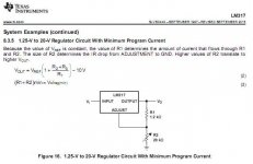
Texas Instr datasheet shows values from 120 to 1k2 als R1 . 1k2 as the minimum program current as they call it.
C2 diminishes as R4 goes to even 560 ohm . So If I want R4 more like 5k6 , R5 560k and C2 47u to 100uF ?
If you want to evaluate a particular type, it can be done in a matter of minutes on a breadboard
We can't evaluate without propper measuring equiment. That's why I depend on you.
C2 diminishes as R4 goes to even 560 ohm . So If I want R4 more like 5k6 , R5 560k and C2 47u to 100uF ?
If you want to evaluate a particular type, it can be done in a matter of minutes on a breadboard
We can't evaluate without propper measuring equiment. That's why I depend on you.
In the TI datasheet (www.ti.com/lit/ds/symlink/lm117.pdf), I was unable to find a mention of R1 > 243 ohm (except in a special application using a LM329, but that is not a standard use).
I probably missed it.
Anyway, the 317 will still function with values much larger than 240 ohm, but it will not meet its datasheet specs, that's understood.
If you have a particular type of low-power regulator in mind, I might be able to test it: in sim, if a reliable model is available, or (preferably) in reality if I have such a IC in my drawers or if I can get hold of one without too much hassle
Edit:
I found an earlier document where a regulator with a minimum program current example here, page 6:
https://www.sparkfun.com/datasheets/Components/LM317.pdf
No other details are given, which means that the normal specs are no more supported, just the functionality.
It has apparently been expurgated from later versions.
Last edited:
No other details are given, which means that the normal specs are no more supported, just the functionality.
It has apparently been expurgated from later versions.
The question is , how much it deviates from "normal specs" and in what way.
I don't have another low power regulator in mind , as I said before the more expensive T.I & L.T regulators are less easy for me to buy and the best come in awful stupid tiny smd. The LM317 can be low power enough. I could make it very low quiescent current with ref-opamp-Pmosfet but have no idea how noise & PSRR will be. Paying 5 euro for something like the LT1963A which still needs the DeNoiser is going to far (for me).
A good compromise will be 390 or 470 ohm for R1 and 3k3 to 3k9 for R4 leaving the rest as it is.
Attachments
317 style regulators need a minimum current as the q current would cause the output voltage to rise without it. If the external load is above this minimum the programming resistors can me an order of magnitude larger values or more and the adjustment pin cap proportionately smaller. Data sheet lists minimum current and swows values that provide it with no external load. Another 2 great LV designs!

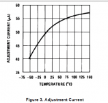
It is easy to compute, at least for temperature because a graph is provided in the DS:The question is , how much it deviates from "normal specs" and in what way.
Between 0 and 50°C, the variation is ~5µA.
If you use the maximum 1K2 resistor, that is 6mV, ~0.5% of 1.25V or 0.01%/°C of additional drift.
Attachments
You keep bringing up temperature , but that's about the least interesting spec of a regulator especially for audio.
What the datasheets don't specify is how line/load regulation , PSRR , output impedance , noise change when you deviate from their "ideal" 240 ohm application.
What the datasheets don't specify is how line/load regulation , PSRR , output impedance , noise change when you deviate from their "ideal" 240 ohm application.
They do specify the adj-current change for load current and ΔV:

You can then do the same math as I did, for 0.2µA or 5µA, depending on your state of mind: optimistic or not.
I concentrated on temperature, because that's where most of the effects will be felt.
Since no noise current is specified, it would be difficult to extrapolate for noise, but we can be sure of two things: it increases (by an unknown amount) with the impedance level, but fortunately it does not matter, because the denoiser becomes proportionately more effective with a higher load impedance
Attachments

One more thing: PSRR and output impedance flaws will also be polished off by the denoiser in the same way.
The corresponding static parameters, line regulation and load regulation won't.
To summarize: increasing the resistance level in a denoiser-equipped regulator will have little or no effect on the dynamic performances, but the static parameters degradation will remain totally unaffected
The corresponding static parameters, line regulation and load regulation won't.
To summarize: increasing the resistance level in a denoiser-equipped regulator will have little or no effect on the dynamic performances, but the static parameters degradation will remain totally unaffected
Good morning, gentlemen.
I’m a little confused with all these diagrams, in order to have +24 v output to power a preamp, what diagrams should I take and what value of resistors should I choose?
By thanking you in advance.
TOTO 34
I’m a little confused with all these diagrams, in order to have +24 v output to power a preamp, what diagrams should I take and what value of resistors should I choose?
By thanking you in advance.
TOTO 34
Good morning, gentlemen.
I’m a little confused with all these diagrams, in order to have +24 v output to power a preamp, what diagrams should I take and what value of resistors should I choose?
By thanking you in advance.
TOTO 34
I'm confused too.
Are caps non polarized type?
I can't see from schematic.
I agree: the project started with the denoiser, and the nonoiser grafted itself to the thread, which didn't contribute to clarity.
Here is an updated denoiser schematic, including the polarities of capacitors
The voltages of the capacitors have to match the output voltage (and input in the case of C4, which is optional: in principle, it should already be there).
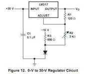
The calculation of the output voltage is just like an ordinary 317 reg: use R1 and R2 in the formula provided in the datasheet (for 24V, R2 would need to be 4K1).
For the nonoiser, the adapted schematic is here:
The base formula is no longer usable, but I provided exact and approximate alternatives here:
D-Noizator: a magic active noise canceller to retrofit & upgrade any 317-based V.Reg.
Attachments
- Home
- Amplifiers
- Power Supplies
- D-Noizator: a magic active noise canceller to retrofit & upgrade any 317-based VReg