Do you need to store settings for switching between different inputs (i.e. do you have to "control" the virtual knob position)?
If not, an alternative to a rotary encoder if you need smooth feel is to use a cheap linear pot off a rail into a MCU ADC and read the value.
Yes, I do, that's the whole point. That's why I am only using rotary encoders and motorized faders.
Do you need to store settings for switching between different inputs (i.e. do you have to "control" the virtual knob position)?
If not, an alternative to a rotary encoder if you need smooth feel is to use a cheap linear pot off a rail into a MCU ADC and read the value.
Chris,
Let me give a bit more context to my answer.
The reference setup that I am building is a crossover between:
- an audio interface (multiple ADCs and DACs)
- a modular synthesizer (lots of oscillators, filters, etc.)
- a control surface (lots of buttons, encoders, faders, displays, etc.)
- a mixing console
The setup itself is not a "product", it's a particular configuration for a highly modular system. What I am trying to demonstrate is that one can build virtually any kind of audio system with it, and that the resulting system is of high quality and provides a high level of integration.
For the control surface element, my benchmark is the Pro Tools | S6. I am also getting some inspiration from the grandMA3, which is a lighting control system. This is part of my attempt to demonstrate that a setup like the one linked above could be used to control not just sound, but also light or video. And what all these control surfaces have in common is that they only use soft controls:
- Momentary switches rather than toggle buttons
- Rotary encoders rather than potentiometers
- Motorized faders rather than purely manual ones
This allows the software to instantly preset any configuration.
For the modular synthesizer aspect, things get even more interesting. There, I am really trying to reinvent the way modular synthesis is done. Today, once a patch has been created (connecting cables between ports and setting the levels of potentiometers or sliders), sound can be recorded out of it, but it can never be recreated in a perfectly identical fashion. One could take notes of the patch's configuration, but fine potentiometer adjustments will most likely be lost when recreating a similar patch.
Of course, some musicians on the romantic side of the spectrum might argue that the transient nature of a modular patch is a critical part of its unique charm. I understand and respect this argument, but I do not buy it for myself. And I like to believe that I am not the only one in that position.
Another answer to the problem is to use an integrated synthesizer. This is what people have done successfully since the late 70's or early 80's, but then all the fun of plugging cables is gone. My solution to that problem, as described earlier on this thread, is to go from mono patch cables to stereo patch cables, whereby the left channel is used to carry the audio or CV signal, and the right channel is used to carry a digital signature for the signal. Another part of the solution is to ensure that all ports can be used either for audio or for CV, and either as input or output. Furthermore, all ports are coupled to an audio CODEC, so that a digital twin of the signal (and I really mean signal, not just the signature for the signal) is available in the digital domain.
What this design allows you to do is to create a patch with cables and rotary encoders settings and have it instantly recorded by the system. This patch thereby becomes a preset and can be reset in the future, without having to use any cable nor having to turn any encoder. In and by itself, this would be a major innovation in the field of modular synthesis.
But it does not stop there. What makes modular synthesis particularly appealing is that it allows you to mix analog and digital signals very effectively. Obviously, early modular synthesizers like the ones designed by Moog were 100% analog. But recent modules developed by vendors like Mutable Instruments are almost entirely digital (most modules are driven by an ST32 MCU). What I want is to marry the two. In order to understand how it will work, it might be helpful to take a look at existing systems.
Take my Sequential Pro 2 for example. This is a hybrid monophonic synthesizer, with digital oscillators (they are digital to ensure stability) and analog filters (they are analog because they "sound" better). I would like to recreate this synthesizer in a modular fashion. But this synthesizer is monophonic only. Now take a look at something similar but much more advanced: the Schmidt synthesizer. This is a truly analog synthesizer, but with digital presets, and it is fully polyphonic (8 voices). I would like to recreate that synthesizer as well.
Why do I want to do that? Because the Schmidt synthesizer comes at a hefty €19,900. And if you're not totally happy with its design, there is nothing you can do about it. If you want 10 voices instead of 8, you're stuck with 8, or you have to buy two of them. If you want a slightly different oscillator, or a different filter, you're out of luck. If we could recreate this synthesizer with OTO™ bricks of a similar cost, we would prove the point. And if we could recreate it at an even lower cost, we would prove the point even more.
What I am trying to build is a system that would let virtually anyone with reasonable programming skills recreate any of these instruments, using LEGO®-like bricks. And the most important brick for this purpose will be the P4 brick, or to be more precise, a full collection of P4 bricks.
To start with, these bricks will have four Audio/CV ports that can be used as inputs or outputs. And to drive these IOs, they will have a built-in AD1938 4 ADC/8 DAC audio CODEC. Pairs of DAC channels will be summed in order to further increase SNR. But we won't stop there: we will create dozens of variations of this brick, each with its own IC. One will come with a built-in ST32 MCU to create sounds in the digital domain. But all the others will come with a modern replica of a vintage analog IC, like the ones listed on this sheet (rows 26 and below). This will allow creators to assemble a custom modular synthesizer using a plate as breadboard for 9 bricks, and a tray as breadboard for 6 plates. For example, my reference setup makes room to recreate all Mutable Instruments modules and most of the Korg Volta instruments (Cf. Instruments).
Of course, all this begs the question of why we are doing all this work on this particular forum. Well, all this is largely happening by accident. As you might remember, the original project was focused on the audio interface part of the system. But as our understanding of the system evolved, the concept of a submodular architecture emerged, and it was too good to ignore.
Nevertheless, the source and digital line aspects of the project remain critically important, for one main reason: we want to raise the bar in terms of sound quality for modular systems. In order to better understand that point, one could look at the studio built by Canadian electronic music producer deadmau5 (see attached picture). On one side, lots of modular modules, like the ones from Mutable Instruments. On the other, an all-analog Rupert Neve 5088 mixer. Clearly, we cannot compete against the romantic appeal of a high-voltage and discrete mixer like the 5088. But if we could significantly increase the sound quality of analog modular oscillators and filters by bringing them into the digital domain right from the source (from within our P4 bricks) and implement a stem mixing and mastering topology by using AK5578EN-powered ADC blocks and AK4499EQ-powered DAC blocks, I like to believe that we could provide producers like deadmau5 with an attractive alternative.
In a nutshell, such is the dream for this particular project.
Attachments

Debouncing the Rotary Encoder
Here is a great article on debouncing for rotary encoders. After having read it, I am convinced that I should build a prototype of the new E1 brick on the breadboard before designing its circuit, because it is not clear that I will need any hardware debouncing at all, or whether such a circuit will require a Schmitt trigger. Based on my experience with the Knob G Click, it's actually possible that the hardware debouncing circuit was designed too aggressively, and that using a 0.47μF capacitor instead of a 10nF created some timing problems.
Here is a great article on debouncing for rotary encoders. After having read it, I am convinced that I should build a prototype of the new E1 brick on the breadboard before designing its circuit, because it is not clear that I will need any hardware debouncing at all, or whether such a circuit will require a Schmitt trigger. Based on my experience with the Knob G Click, it's actually possible that the hardware debouncing circuit was designed too aggressively, and that using a 0.47μF capacitor instead of a 10nF created some timing problems.
But all the others will come with a modern replica of a vintage analog IC, like the ones listed on this sheet (rows 26 and below).
Clearly, these advanced P4 bricks will need to be higher than the regular 22mm tall bricks. Ideally, they'll be perfect 32mm cubes, and we'll mount the analog IC of each brick on a DIP socket. That way, we should be able to create a small collection of generic P4 bricks, each capable of hosting a wide range of oscillators, filters, and amplifiers. This would further increase the modularity of the platform.
Board Stacking
Good news: we just realized that the indexing studs on the ER8 connectors are only 1.07mm tall. What that means is that we could mount such connectors on both sides of the same 2.4mm-thick PCB, and have them share the same through holes without any interference. This would allow the unlimited stacking of our boards much like shields on an Arduino board, but using high pin-count connectors instead of regular 0.1" headers. This will make it a lot easier to create bricks of different heights when a lot of components need to be crammed within a single brick (like the analog-powered P4 bricks introduced earlier).
Good news: we just realized that the indexing studs on the ER8 connectors are only 1.07mm tall. What that means is that we could mount such connectors on both sides of the same 2.4mm-thick PCB, and have them share the same through holes without any interference. This would allow the unlimited stacking of our boards much like shields on an Arduino board, but using high pin-count connectors instead of regular 0.1" headers. This will make it a lot easier to create bricks of different heights when a lot of components need to be crammed within a single brick (like the analog-powered P4 bricks introduced earlier).
36mm Bricks
This morning, we took a closer look at the Cherry MX form factor, which spaces keys by 0.75", or 19.05mm. Therefore, two keys need 36.1mm. What that means is that if we were to increase the size of our bricks from 32mm × 32mm to 36mm × 36mm, we'd be able to make bricks with 4 Cherry MX keys (the missing 0.1mm is the thickness of a sheet of paper, which is probably fine).
Going that way would bring all sorts of benefits, beyond the simple ability to make a cool quad Cherry MX brick. But let's talk about that first. Cherry MX is really attractive, because there is a huge ecosystem built around it. And when looking for an excellent momentary switch with all kinds of options, one would have a harder time finding a better platform.
Somehow, these switches are not very popular with audio processing systems, but they are the norm for lighting control systems like the grandMa3 mentioned earlier. And what makes them so attractive is that they come with a wide range of options regarding operating force, pre-travel distance, total travel distance, audible click, tactile click, clicking frequency, profile, color, and illumination. Not only that, but its easy and cheap to get key caps in all kinds of colors and finishes and have them printed with custom labels.
But as mentioned above, the benefits do not stop there.
36mm is a nice number because it's really close to 36.1mm, which is equal to 0.75". In other words, if your tolerance is paper thin, 36mm gives you a unit of measurement that works equally well whether you work in metric or imperial.
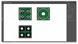
But 36mm would also give us quite a bit of wiggle room to make our bricks less crazy tight. For example, the attached sketches show what the P4, E1, and E4 bricks would look like.
For the P4 brick, we would have a lot more room for the LEDs, allowing us to separate the bargraphs for two adjacent ports a lot more, which would improve readability. It would also allow us to increase the width of the PCB's middle section, which would increase rigidity and reduce the risk of mechanical fracture. It would also allow us to provide more space between the LED board and the TRS connectors, thereby relaxing some assembly tolerances for the soldering of the TRS connectors. Most importantly, it would allow us to space the ports out a bit more, matching what is done by conventional synthesizers like the Behringer Neutron.
For the E1 brick, it would allow us to make our LED ring quite a bit larger, thereby providing more clearance between the LEDs and the encoder's pins. It would also make it possible to use an even larger knob cap, which is quite nice.
And for the E4 brick, it would allow us to space the encoders out a bit more, while preserving an evenly-spaced layout when repeating across multiple matching bricks. Most importantly, it would provide more clearance between the encoders and the brick's frame, allowing us to relax PCB assembly tolerances.
Finally, another benefit would be to provide enough room to go from 30 circuits to 40 circuits for the ER8 connectors, and that would allow us to go switch from Hirose back to Samtec. Doing so, the ERM8 would give us four mating height options instead of 2: 7mm, 10mm, 13mm, and 14mm (instead of just 7mm and 9mm), and that would give us a lot more flexibility when dealing with components of varying heights.
So here we go, 36mm is the new standard!
This morning, we took a closer look at the Cherry MX form factor, which spaces keys by 0.75", or 19.05mm. Therefore, two keys need 36.1mm. What that means is that if we were to increase the size of our bricks from 32mm × 32mm to 36mm × 36mm, we'd be able to make bricks with 4 Cherry MX keys (the missing 0.1mm is the thickness of a sheet of paper, which is probably fine).
Going that way would bring all sorts of benefits, beyond the simple ability to make a cool quad Cherry MX brick. But let's talk about that first. Cherry MX is really attractive, because there is a huge ecosystem built around it. And when looking for an excellent momentary switch with all kinds of options, one would have a harder time finding a better platform.
Somehow, these switches are not very popular with audio processing systems, but they are the norm for lighting control systems like the grandMa3 mentioned earlier. And what makes them so attractive is that they come with a wide range of options regarding operating force, pre-travel distance, total travel distance, audible click, tactile click, clicking frequency, profile, color, and illumination. Not only that, but its easy and cheap to get key caps in all kinds of colors and finishes and have them printed with custom labels.
But as mentioned above, the benefits do not stop there.
36mm is a nice number because it's really close to 36.1mm, which is equal to 0.75". In other words, if your tolerance is paper thin, 36mm gives you a unit of measurement that works equally well whether you work in metric or imperial.
But 36mm would also give us quite a bit of wiggle room to make our bricks less crazy tight. For example, the attached sketches show what the P4, E1, and E4 bricks would look like.
For the P4 brick, we would have a lot more room for the LEDs, allowing us to separate the bargraphs for two adjacent ports a lot more, which would improve readability. It would also allow us to increase the width of the PCB's middle section, which would increase rigidity and reduce the risk of mechanical fracture. It would also allow us to provide more space between the LED board and the TRS connectors, thereby relaxing some assembly tolerances for the soldering of the TRS connectors. Most importantly, it would allow us to space the ports out a bit more, matching what is done by conventional synthesizers like the Behringer Neutron.
For the E1 brick, it would allow us to make our LED ring quite a bit larger, thereby providing more clearance between the LEDs and the encoder's pins. It would also make it possible to use an even larger knob cap, which is quite nice.
And for the E4 brick, it would allow us to space the encoders out a bit more, while preserving an evenly-spaced layout when repeating across multiple matching bricks. Most importantly, it would provide more clearance between the encoders and the brick's frame, allowing us to relax PCB assembly tolerances.
Finally, another benefit would be to provide enough room to go from 30 circuits to 40 circuits for the ER8 connectors, and that would allow us to go switch from Hirose back to Samtec. Doing so, the ERM8 would give us four mating height options instead of 2: 7mm, 10mm, 13mm, and 14mm (instead of just 7mm and 9mm), and that would give us a lot more flexibility when dealing with components of varying heights.
So here we go, 36mm is the new standard!
Attachments
Cherry MX Switch Tester
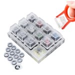
I just ordered this Cherry MX Switch Tester to try different options:
- Cherry MX Red: Soft Linear 45cN - Smooth, no tactile bump
- Cherry MX Black: Firm Linear 60cN - Smooth, no tactile bump
- Cherry MX Blue: Tactile & Clicky 50cN
- Cherry MX Brown: Soft Tactile 45cN - Softer & lighter tactile bump, no click
- Cherry MX Green: Firm tactile & Clicky 80cN
- Cherry MX Tactile Gray: Tactile 80cN - Firm tactile bump, no click
- Cherry MX Clear: Tactile 55cN - Tactile bump, no click
- Cherry MX White: Tactile & Clicky 65cN - Tactile and lighter click switch
- Silent Red: Soft Linear 45cN - Smooth & Silent
- Silent Black: Firm Linear 60cN - Smooth & Silent
- Speed Silver: Soft Linear 45cN - Smooth, no tactile bump, 3.4 mm total travel distance only
- Speed Silver [RGB]: Speed Silver with extra RGB LED light, transparent switch body.
Attachments
Not a bad idea on the key switches. I've used Red and Blue on keyboards. Red has to be bottomed out to actuate. Blue is clicky but it's high in the travel range and soft (not sure if keyboards use 50cN or what). Gray, Green, Clear, or White seem best for this application but I haven't tried them.
Not a bad idea on the key switches. I've used Red and Blue on keyboards. Red has to be bottomed out to actuate. Blue is clicky but it's high in the travel range and soft (not sure if keyboards use 50cN or what). Gray, Green, Clear, or White seem best for this application but I haven't tried them.
I'm really glad that you like it. Slowly but surely, we're converging toward a form factor that allows us to do all the things that we had in mind originally, but in a much more practical manner.
As far as the type of switch is concerned, I think that we would leave it entirely to the user. What I mean by that is that we would not ship any Cherry MX switches by default, just the bare bricks, and we would let users buy the switches and caps that they want.
In fact, I suspect that I will use many different switches for my reference setup, because different instruments require different kinds of haptic feedback.
I am really happy about this latest development actually...
DAC Brick?
Now that we have increased the size of our bricks to 36mm × 36mm, it might be time to reconsider our DAC block, and see if we could make it fit within a brick. As a reminder, a block is the size of a plate, which would now be 110mm × 110mm (enough to leave 0.5mm of clearance between two adjacent bricks). A plate can either host 9 bricks or one block. Therefore, a DAC block would be 110mm × 110mm. This earlier (and very naive) post showed how all the components would fit on a 70mm × 35mm PCB. Of course, it would not have worked, because we did not have enough room for vias. But most of the components were just on one side of the board. Therefore, with components on both sides, we would probably have been fine with that form factor.
Now, we only have 36mm × 36mm within a brick, and we probably should keep the PCB at about 32mm × 32mm. Therefore, there is no way that we could fit all the components within a single board. But what if we split the board in two, with the core DAC on one board and the power supplies on the other? This is what AKM's reference design is doing, so I see no reason why we could not do that as well.
If we were going down that road, the DAC brick would have the following boards:
- Base board (with power supply circuits)
- DAC board (with the AK4499EQ)
- Port board (with one XLR port or four mini XLR ports)
And I am willing to bet that such a stack would not be higher than 36mm, making the brick a perfect square. I am not saying that it is possible, but it certainly is quite attractive...
Last edited:
3 MCUs per Plate
Up until now, our plan was to have a single STM32H743 MCU per plate to drive nine bricks. But our bricks have become slightly bigger, therefore potentially more powerful. And the idea of putting the full AK4499EQ-powered DAC on a single brick means that we probably need more power at the plate level. Also, nine bricks for a single MCU is probably too much and would require quite a bit of multiplexing in order to get everything right. Instead, we're probably better off putting multiple MCUs on a plate. But the question then becomes: how many of them?
Obviously, we cannot put one for each and every brick, because it would be wasteful and it would create many issues on the USB front. Therefore, if we want to keep things fairly balanced, we only have two options: one MCU for every 3 bricks, or one MCU for every 2 bricks. The following analysis gave us the best answer: one MCU for every 3 bricks, which means 3 MCUs on every plate.
This is really nice, because it will give each and every brick the following dedicated interfaces (no multiplexing):
- 1 × UART Interface
- 1 × USART Interface
- 1 × SPI Interface
- 1 × I²C Interface
- 1 × I²S Interface
- 1 × ADC Interface
- 1 × PWM Interface
- 3 × General Purpose Timers
- 1 × Low Power Timer
Of course, this will increase the cost of our BOM (by about $20 per plate), but this is negligible compared to the cost of bricks. And it will require a USB hub to be integrated within every plate, but that should not be a problem.
Now, we need to update the OTOBUS™ accordingly.
Last edited:
40-Circuit OTOBUS™
This sheet outlines what a 40-circuit OTOBUS™ would look like. With so many interfaces directly available, I see no need to add other things on the other ER8 connector. Therefore, we should mirror the two connectors. This would bring three major benefits:
- Fool-proof design
- Ability to rotate a brick 180° on its plate
- Shorter and simpler traces on the PCB
And with this design, we still get 4 unconnected pins for future extensions.
With the mirror design that we have adopted, pins 21 through 40 would face the outer edges of the board. The reason for this layout is that many boards are likely to use one layer for ground. Therefore, we've put most of our GND pins on that side of the connectors, with power pins facing the inside of the board. But we've also included two inside-facing GND pins. All this should make routing a bit easier.
Note: the only major interface missing is an LCD interface, but I see no need for this interface on the OTOBUS™. The reason for it is simple: most of the displays that we need can be driven over SPI, and if we need a bigger display, we will probably go for an embedded smartphone, which will give us the very best touchscreen we could ever get, an unbeatable price, and an unmatched development environment for complex user interfaces. And in the very unlikely case where we would really need an LCD display, we could always add a dedicated MCU within the brick itself. There simply is no need to waste 40 pins (what the Fusion for STM32 v8 board is allocating for their LCD interface) for something that will never be used.
Last edited:
SPI bus requires a dedicated Slave_Select line for each SPI device.
Isn't that what I have done with pin 11?
Mill-Max Super Low-Profile Sockets
We just found the Mill-Max Super Low-Profile Sockets. These will be great to mount the LED board on the P4 brick's base board in order to provide sufficient clearance for our LED pipes. These connectors bring the mating height of conventional 0.1" header from 6.6mm to 3.94mm. This will allow us to reduce the total height of the brick to a round 20mm.
We just found the Mill-Max Super Low-Profile Sockets. These will be great to mount the LED board on the P4 brick's base board in order to provide sufficient clearance for our LED pipes. These connectors bring the mating height of conventional 0.1" header from 6.6mm to 3.94mm. This will allow us to reduce the total height of the brick to a round 20mm.
Isn't that what I have done with pin 11?
If you have one SPI device to control, that works. If you have two, then not.
If you have one SPI device to control, that works. If you have two, then not.
I see. Well, I am assuming that many of the GPIOs used for other interfaces provided by the bus could be used for additional Slave Select circuits, right?
...many of the GPIOs used for other interfaces provided by the bus could be used for additional Slave Select circuits, right?
Presumably so. Just thought it might be worth mentioning.
Presumably so. Just thought it might be worth mentioning.
Absolutely! Thank you for that. Many pairs of eyes are always better than a single one, especially when the latter is so new to this game...
Cherry MX Switch Tester Received
Here is the Cherry MX Switch Tester next to scale sketches of the E1, E4, and P4 bricks. These switches are amazing , and this little tester is a great way to evaluate them. Clearly, for triggering synthesized sounds, the Silent Red (Soft Linear 45cN - Smooth & Silent) is a great alternative to the LP4 that we were planning to use, because it's really soft (lowest operating force of all), and totally silent (no tactile bump). But most importantly, this demonstrated to me the benefit of letting users pick their own switches. Bottomline: we will use these for most of our instruments. This will give them a unique look &feel that some will love and others will hate, and that's probably a good thing.
Here is the Cherry MX Switch Tester next to scale sketches of the E1, E4, and P4 bricks. These switches are amazing , and this little tester is a great way to evaluate them. Clearly, for triggering synthesized sounds, the Silent Red (Soft Linear 45cN - Smooth & Silent) is a great alternative to the LP4 that we were planning to use, because it's really soft (lowest operating force of all), and totally silent (no tactile bump). But most importantly, this demonstrated to me the benefit of letting users pick their own switches. Bottomline: we will use these for most of our instruments. This will give them a unique look &feel that some will love and others will hate, and that's probably a good thing.
Attachments

- Home
- Source & Line
- Digital Line Level
- 8 × AK5578EN + 8 × AK4499EQ ADC/DAC Boards