Resized Bricks
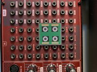
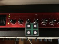
Here are the resized bricks in context:
- Ports on P4 are now even more widely spaced than on the Behringer Neutron, which is a good thing.
- The LED ring on E1 is probably too wide and could be reduced by 1 to 1.5mm in diameter.
- The encoders on E4 are still closer than on my Focusrite, but they should be totally usable.
I think we're good enough for now...
Attachments
Silicon Serial Number
As I am working on the specification for the OTOBUS™, I am wondering whether we should dedicate one pin for a unique serial number using the 1-Wire® protocol. This would allow us to implement unique serial numbers on every brick using the DS2401. There are many applications for such a unique serial number, but one would be to automate the configuration of a brick on a plate by looking up some kind of online registry, or at the very least a local lookup table that would be manually updated by the end-user. The only concern I have is that this chip is quite large (3.7mm × 4mm), and I would hate to lost that much space on every brick. Anyone has any experience with smaller components?
As I am working on the specification for the OTOBUS™, I am wondering whether we should dedicate one pin for a unique serial number using the 1-Wire® protocol. This would allow us to implement unique serial numbers on every brick using the DS2401. There are many applications for such a unique serial number, but one would be to automate the configuration of a brick on a plate by looking up some kind of online registry, or at the very least a local lookup table that would be manually updated by the end-user. The only concern I have is that this chip is quite large (3.7mm × 4mm), and I would hate to lost that much space on every brick. Anyone has any experience with smaller components?
As I am working on the specification for the OTOBUS™, I am wondering whether we should dedicate one pin for a unique serial number using the 1-Wire® protocol. This would allow us to implement unique serial numbers on every brick using the DS2401. There are many applications for such a unique serial number, but one would be to automate the configuration of a brick on a plate by looking up some kind of online registry, or at the very least a local lookup table that would be manually updated by the end-user. The only concern I have is that this chip is quite large (3.7mm × 4mm), and I would hate to lost that much space on every brick. Anyone has any experience with smaller components?
I take that back: it's available in WLP package, which is clearly small enough. Now, I just need to make sure that the PCB assembly service provider will be able to handle them.
SAI Interface
After further review of the STM32H743's datasheet, it appears that the MCU offers 3 × I²S Interfaces plus 4 × SAI interfaces (Serial Audio Interface), which seems to be ST's take on I²S (Cf. presentation). Since our bricks are mostly geared toward audio applications, we should really include this extra interface to the OTOBUS™, which means that we have to lose the low-power timer pin, and we do not have any unconnected pins left. Also, I took another look at the 1Wire® protocol, and we certainly do not want to implement it in software (this would consume way too much resources). Therefore, if we want to go down that path, we might have to dedicate for it either the I²C interface or the UART interface.
This MCU is awesome!
And I sure am glad that we decided not to stick with the mikroBUS specification, because we would have lost direct access to most of the goodness that this $10 chip has to offer...
Last edited:
Supporting I2S at all is one thing. Doing it well enough to sound decent is another. It would take some testing to see how well STM32H743 could perform in a music performance and or recording/playback type application.
We have to use the STM32H743 in order to use the Thesycon U-HEAR firmaware as a replacement for the XMOS, right? If that is the case, we have to use I²S, because it's the only way I know for the STM32H743 to integrate with a DAC or an ADC. Did I miss something?
38mm, not 36mm
Somehow, I got my maths wrong yesterday. Two Cherry MX keys are spaced by 0.75", which is 19.05mm, which means that a brick should be twice as large, that is about 38mm, not 36mm! This should make our TRS ports perfectly spaced, and it will provide the right amount of clearance between encoders. Not only that, but it will also relax some constraints for the DAC brick.
Somehow, I got my maths wrong yesterday. Two Cherry MX keys are spaced by 0.75", which is 19.05mm, which means that a brick should be twice as large, that is about 38mm, not 36mm! This should make our TRS ports perfectly spaced, and it will provide the right amount of clearance between encoders. Not only that, but it will also relax some constraints for the DAC brick.
We have to use the STM32H743 in order to use the Thesycon U-HEAR firmaware as a replacement for the XMOS, right? If that is the case, we have to use I²S, because it's the only way I know for the STM32H743 to integrate with a DAC or an ADC. Did I miss something?
It doesn't appear to have the specs needed for cutting edge hi-fi audio. Native DSD512 support? 2 or 4-channels of 24-bit 384kHz PCM (DXD)? Best achievable MCLK jitter?
Maybe fine for MIDI control signal data converters, and other less demanding uses.
Last edited:
It doesn't appear to have the specs needed for cutting edge hi-fi audio. Native DSD512 support? 2 or 4-channels of 24-bit 384kHz PCM (DXD)? Best achievable MCLK jitter?
Maybe fine for MIDI control signal data converters, and other less demanding uses.
No, there’s no reason it wouldn’t be as good as an XMOS or CMedia chip. MCLK jitter is irrelevant because you’re not using a recovered MCLK for async USB audio.
DSD and similar are marketing requirements. Regardless, it does support all of the above. From their product page:
32-bit PCM sample format up to 768 kHz sampling rate
Native DSD up to DSD1024
DSD over PCM (DoP) up to DSD256
...DSD and similar are marketing requirements. Regardless, it does support all of the above...
Good news. How many I2S channels at those data rates?
Good news. How many I2S channels at those data rates?
Thought I saw it on their site somewhere (Thesycon) and it was 2 in 2 out. It’s probably limited by either I/O bandwidth somewhere internally at those high rates or by the number of available hardware SAI peripherals that can operate however Thesycon is using them.
What was your concern about MCLK about?
What was your concern about MCLK about?
Its really a more general concern. Some dacs seem exquisitely sensitive to clock signal quality, not just MCLK. Noise, jitter, slow edges, whatever, on other I2S signals can be issues when trying to get a Sabre dac run in fully synchronous 128_fs mode (lock status = 1) with DPLL_bandwidth set = 0. Also, some people report sound quality changes with XMOS chips (and in some dacs) when the XMOS VCO power pin is not properly filtered and or regulated. In other words, despite theory about meeting setup times and so forth, in practice we sometimes may find unexpected complications with audible effects (to some people). No doubt with enough time and effort all issues can be fully resolved using conventional engineering methods. That may or may not ultimately result in finding a particular chip, it firmware, and or drivers to be unsuitable for one's application. Only testing will tell if there are problems not stated in manufacturer literature. Of course, carefully examining the literature and specs it at least a start.
Last edited:
Well, that sounds like a Sabre specific problem. There’s no theory about setup and hold, it’s reality. The fact that the Sabre has an un-defeatable PLL / ASRC is a Sabre exclusive problem.
Either way, MCLK isn’t generated by the USB receiver, which means you don’t need the other clocks to be generated from the receiver chip of your choice either. You can and should run the I2S ports in slave mode and generate your own BCK and WCK if you are that paranoid. Anyone complaining about jitter on signals that come out of what is still basically an MCU is doing it wrong.
You should also note that this approach is not any “softer” than an XMOS. The XMOS is just a general purpose processor also, and almost every underlying implementation of an I2S peripheral is very similar to a SPI peripheral.
Last edited:
You can and should run the I2S ports in slave mode and generate your own BCK and WCK if you are that paranoid.
Tried that with AK4137 and ES9038Q2M. AK VCO did not track DSD_CLK as well as it did a 25MHz reference clock. Sound quality was worse running it in slave mode. That said, I believe Allo runs XMOS and even RPi successfully in slave mode. The difference between their situation and mine was likely that AK4137 VCO was also the reference for upsampling performed by the AK, which adds a complicating factor. Perhaps also worth noting, Allo had to work with XMOS and ESS to find a bug in XMOS firmware in order to get Sabre to lock with XMOS in slave mode and with DPLL = 0 at DSD512. Only point is it doesn't always turn out to be as straightforward as we might first estimate.
Last edited:
Tried that with AK4137 and ES9038Q2M. AK VCO did not track DSD_CLK as well as it did a 25MHz reference clock. Sound quality was worse running it in slave mode. That said, I believe Allo runs XMOS and even RPi successfully in slave mode. The difference between their situation and mine was likely that the VCO was also the reference for upsampling performed by AK4137, which adds an additional complicating factor.
What does a VCO or ASRC have to do with anything? You take MCLK and divide it by 256 or whatever for the word clock and 4 or 8 for bit clock via synchronous counters or whatever method you choose. I’m not sure you understand how this all works or you choose to complicate it with two ASRCs for no reason. You seem to understand a very narrow slice of things and try to apply it to everything. Anyway, I told you how to generate I2S signals with basically the same jitter as your reference MCLK. If you choose to do something else then that’s fine but don’t say you tested it, because you haven’t.
Last edited:
What does...
Please see edits to last post.
Regarding why I would complicate things with two ASRCs was for a very good reason: Its how Benchmark DAC-3 works.
Please see edits to last post.
One can't help if you are using two ASRCs and one in a DAC which may or may not be buggy, when you should have none.
...when you should have none.
Yep, in theory I would agree. In practice, not necessarily.
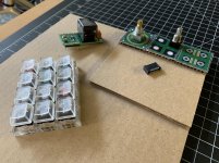
Sample Components
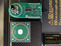
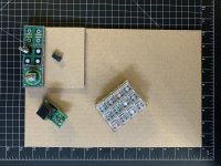
Here are some of the sample components that I received today, mounted on cardboard mockups of a tray (14.5" × 9"), plate (4.5" × 4.5"), and brick (1.5" × 1.5"). The two encoders (from CUI and CTS) have an awesome detent feel (much smoother than the Alps, yet totally positive). The pair of Hirose ER8 connectors is for 30 circuits while we will use 40-circuit alternatives from Samtec, but they feel great, smooth during mating/unmating yet perfectly positive in their connection. And the NKK Switch ISC15ANP4 mounted on the OLED Switch Click feels actually pretty good, and we might have some applications for it. Overall, I am really happy with these components.
Here are some of the sample components that I received today, mounted on cardboard mockups of a tray (14.5" × 9"), plate (4.5" × 4.5"), and brick (1.5" × 1.5"). The two encoders (from CUI and CTS) have an awesome detent feel (much smoother than the Alps, yet totally positive). The pair of Hirose ER8 connectors is for 30 circuits while we will use 40-circuit alternatives from Samtec, but they feel great, smooth during mating/unmating yet perfectly positive in their connection. And the NKK Switch ISC15ANP4 mounted on the OLED Switch Click feels actually pretty good, and we might have some applications for it. Overall, I am really happy with these components.
Attachments
Field Trip
Yesterday, I visited a couple of friends that I met on this forum, and I got an awesome crash course on DAC design and analog circuits. Many things came out of it, the following among them:
- I should read The Art of Electronics.
- I should review the connectors from Lemo and Neutrik.
- I should review the OS-CON capacitors.
- I should review the Muses integrated circuits.
- Oscillators should face away from the DAC's IC.
- The OTOBUS™ connectors should be mirrored for redundancy.
The last point is probably the most important one. As mentioned earlier, bricks will be mounted on a plate through a pair of 40-circuit ERM8 connectors. These two connectors will have the exact same set of pins. As a result, the bricks will be reversible. But another side benefit of this design is that it will bring some level of redundancy, making the same circuit available through two separate pins. That way, if a pin of one connector fails, a redundant pin should remain available for the same circuit on the other connector. Of course, this would require that both pins are connected to the same circuit on the brick's board. But if we do a good job at laying our PCBs out, this should not be too difficult.
Last edited:
- Status
- This old topic is closed. If you want to reopen this topic, contact a moderator using the "Report Post" button.
- Home
- Source & Line
- Digital Line Level
- 8 × AK5578EN + 8 × AK4499EQ ADC/DAC Boards