More on the P4 Brick
I have looked at all the major manufacturers, and I cannot find a better TRS connector than the Kobiconn 161-MJ355W-EX. Therefore, we won't be able to give our P4 4-TRS ports a perfect layout. But we could turn this problem into an opportunity by using the bezel space for something useful: VU meters. On my Focusrite Clarett 8Pre, the 6-segment VU meter is actually quite useful, and having a 5 or 6-segment VU meter for each and every Audio/CV port on a modular synthesizer would be totally unique and totally awesome. I do not think that we could fit 6-segment assemblies (we need one per port, therefore four per brick), but 5-segment versions might work. Of course, these would need to be built out of color reverse-mounted LEDs, or we'd have to make a middle PCB with a large square opening on it. We'll play with both options, but I think we're onto something here...
And as mentioned earlier, Inputs would be blue while outputs would be green. And in order to distinguish Audio ports from CV ports, we could have the audio ports move upward while the CV ports would move downward. Of course, blue and green would be used for levels 1 through 3, while yellow would be used for level 4 and red for level 5.
Last edited:
I have looked at all the major manufacturers, and I cannot find a better TRS connector than the Kobiconn 161-MJ355W-EX. Therefore, we won't be able to give our P4 4-TRS ports a perfect layout. But we could turn this problem into an opportunity by using the bezel space for something useful: VU meters. On my Focusrite Clarett 8Pre, the 6-segment VU meter is actually quite useful, and having a 5 or 6-segment VU meter for each and every Audio/CV port on a modular synthesizer would be totally unique and totally awesome. I do not think that we could fit 6-segment assemblies (we need one per port, therefore four per brick), but 5-segment versions might work. Of course, these would need to be built out of color reverse-mounted LEDs, or we'd have to make a middle PCB with a large square opening on it. We'll play with both options, but I think we're onto something here...
And as mentioned earlier, Inputs would be blue while outputs would be green. And in order to distinguish Audio ports from CV ports, we could have the audio ports move upward while the CV ports would move downward. Of course, blue and green would be used for levels 1 through 3, while yellow would be used for level 4 and red for level 5.
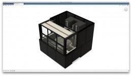
Here is what I have in mind for the VU meters: this brick would have three boards:
- Base Board on which the jacks are soldered.
- LED Board with the four VU meters using 4 × 5 × WS2812C-2020.
- Top Cover Board.
The sketch shows the Base Board + LED Board assembly on the left and the LED Board only on the right. The Top Cover Board is not shown (it won't have anything special on it). This board will be mounted directly on top of the TRS connectors and secured with their respective nuts. Therefore, it won't need any interconnect with the LED Board. But the LED Board will need an interconnect with the Base Board, which remains to be specified.
This would be positively awesome...
Attachments

Bricks Review
We've carefully reviewed all our planned bricks, and it seems that our latest form factor should properly accommodate all of them. Therefore, we're good to go with this latest design iteration. First, we'll redesign the E1 brick. Then, we'll do the P4, because it will include an entry-level audio CODEC (TI TLV320AIC34), which should give us a first experience with audio signal processing before we tackle the design of our AK4499EQ-powered DAC board. But before we do any of that, we need to complete the design of the 60-circuit OTOBUS™.
We've carefully reviewed all our planned bricks, and it seems that our latest form factor should properly accommodate all of them. Therefore, we're good to go with this latest design iteration. First, we'll redesign the E1 brick. Then, we'll do the P4, because it will include an entry-level audio CODEC (TI TLV320AIC34), which should give us a first experience with audio signal processing before we tackle the design of our AK4499EQ-powered DAC board. But before we do any of that, we need to complete the design of the 60-circuit OTOBUS™.
Last edited:
AD1938
For the P4 brick (4 Audio/CV ports), the AD1938 seems like a better option than the TLV320AIC34. And the EVAL-AD1938AZ evaluation board is really well documented (yet crazy expensive). I think we'll give it a shot.
For the P4 brick (4 Audio/CV ports), the AD1938 seems like a better option than the TLV320AIC34. And the EVAL-AD1938AZ evaluation board is really well documented (yet crazy expensive). I think we'll give it a shot.
Light Pipes
Looking at this video, it's pretty clear to me that we will need light pipes for the LEDs of the E1 and P4 bricks. It will prevent bleeding from one LED to another, and it will allow us to deal with the fact that on some bricks, the board holding the LEDs might be a few millimeters apart from the top cover board.
For this application, we probably need either the PLPC flush mount countersink design, or the PLPQ square shape design. Both have their pros and cons, but the main benefit is that they can be assembled at the fab with a pick and place machine. We will try both and use the one that provides the best look and feel for the application. But I am willing to bet that we'll go for round ones on the E1 brick and square ones on the P4 brick. The reasons for these choices are as follows:
- Square pipes on the E1 brick could create the bothersome optical illusion that we mentioned earlier.
- Square pipes on the P4 brick for bargraphs will look a lot cleaner.
The only drawback is that at $0.7 a piece, they are really expensive. For the E1 brick, that will add $22 to the BOM, and $14 for the P4. But I do not see any way around that, short of designing custom light pipes.
Fortunately, these light pipes are available in 1mm increments from 3mm to 10mm and must be within 1.27mm of the LED in order to provide the best level of isolation from one LED to another. Also, they work best with LEDs that have a maximum viewing angle of 160°, and the WS2812C-2020 has a viewing angle of 120° to 140° (no official number on the datasheet).
Last edited:
Board Thickness
In order to deal with the challenges of varying component heights, we will take advantage of varying PCB thickness. JLCPCB offers 0.4, 0.6, 0.8, 1.0, 1.2, 1.6, and 2.0mm, while PCBWay adds 0.2 and 2.4mm to the mix. We will probably stick to 1.2, 1.6, and 2.0mm for our boards. This will allow us to adjust the height of a brick in 0.4mm increments, which should be plenty enough.
In order to define the standard height of our bricks, we should look at the P4 brick, which is the one using the tallest component (vertically mounted TRS connector). This component needs 10.2mm between the base board and the top cover board. The base board itself will need two pairs of ER8 connectors to be mounted on the plate's board, and the smallest mating height that we get is 7.15mm. Therefore, with a 1.6mm PCB for the base board and a 1.2mm PCB for the top cover board, we have a 20.15mm stack. This is pretty much as short as our bricks are going to get, which is not too bad.
Sizing Mockups
Here are some sizing mockups for the E1, E4, and P4 bricks.
The first one is for the E1 single encoder brick, standing next to the Knob B Click. Our LED ring will be a tiny bit wider, which is nice. Other than that, this is a pretty straightforward brick as far as user experience is concerned.
The second one is for the E4 quad encoder brick, standing on top of the Focusrite Clarett 8Pre. Here, the encoders are clearly much closer to each other and will need really thin knob caps. This brick should be evaluated in relation to much smaller knobs, such as the ones used by the six small potentiometers on this instrument.
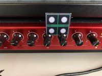
The third and last one is for the P4 quad port brick. This one is standing on top of the Behringer Neutron synthesizer. Here, the ports are slightly closer to each other, but not by much, and this should be totally manageable.
Bottomline, I think we're still good to go with this design.
Here are some sizing mockups for the E1, E4, and P4 bricks.
The first one is for the E1 single encoder brick, standing next to the Knob B Click. Our LED ring will be a tiny bit wider, which is nice. Other than that, this is a pretty straightforward brick as far as user experience is concerned.
The second one is for the E4 quad encoder brick, standing on top of the Focusrite Clarett 8Pre. Here, the encoders are clearly much closer to each other and will need really thin knob caps. This brick should be evaluated in relation to much smaller knobs, such as the ones used by the six small potentiometers on this instrument.
The third and last one is for the P4 quad port brick. This one is standing on top of the Behringer Neutron synthesizer. Here, the ports are slightly closer to each other, but not by much, and this should be totally manageable.
Bottomline, I think we're still good to go with this design.
Attachments
WA-SMSI SMT Steel Spacer
The WA-SMSI SMT Steel Spacer will be better than the PEM K alternative, because with M2 size, its outside diameter is just 5.3mm instead of 6.2mm, and 0.9mm makes the difference between something that will work for us and something that won't... Once again for this type of part, they're not cheap ($0.59 when buying 250), but they'll offer the best option for mounting our top cover plate on bricks like the E1 for which the top cover board cannot be held in place by the brick's control (like will be the case for E4 and P4). Of course, this assumes that the top cover board does not require any electrical circuit, but such is the case for all our bricks so far.
The WA-SMSI SMT Steel Spacer will be better than the PEM K alternative, because with M2 size, its outside diameter is just 5.3mm instead of 6.2mm, and 0.9mm makes the difference between something that will work for us and something that won't... Once again for this type of part, they're not cheap ($0.59 when buying 250), but they'll offer the best option for mounting our top cover plate on bricks like the E1 for which the top cover board cannot be held in place by the brick's control (like will be the case for E4 and P4). Of course, this assumes that the top cover board does not require any electrical circuit, but such is the case for all our bricks so far.
Brick Stacks
We have modeled the stacks for our most important bricks (rightmost columns of the sheet):
- ER8 Pair is the mating height of the pairs of Hirose connectors from the plate to the brick.
- Base PCB is the thickness of the base board.
- Control is the height of the control on which the top cover board is mounted.
- Spacer is the height of the spacer between the base board and the top cover board.
- Washer is the thickness of the washer added between the component and the top cover board.
- Cover PCB is the thickness of the top cover board.
- Height is the total height of the assembly (22mm for all bricks at this point).
- Light Pipe is the length of the required light pipe.
Also, I should mention that the LED board used to display the four bargraphs of the P4 brick will be mounted on the base board using 4 pairs of 2-position SLW and TLW headers (or equivalent). These have a mating height of 6.6mm.
Unfortunately, many boards have to be 2.4mm thick.
But so far, everything seems to be working...
Last edited:
If you mount the LEDs on the top of the board and all the other components on the bottom, and recess the encoder, then the LED ring can be just under the surface of the top plate or lens plate. There may be thin sheets of rough finish thin plastic sheets that could be used as diffusers sitting on top of the LEDs.
All I'm thinking here is that common synth and midi controller knobs with LEDs don't seem to use expensive light pipes. There must be a better way without requiring large scale mass production of custom parts.
All I'm thinking here is that common synth and midi controller knobs with LEDs don't seem to use expensive light pipes. There must be a better way without requiring large scale mass production of custom parts.
If you mount the LEDs on the top of the board and all the other components on the bottom, and recess the encoder, then the LED ring can be just under the surface of the top plate or lens plate. There may be thin sheets of rough finish thin plastic sheets that could be used as diffusers sitting on top of the LEDs.
All I'm thinking here is that common synth and midi controller knobs with LEDs don't seem to use expensive light pipes. There must be a better way without requiring large scale mass production of custom parts.
Light pipes aren't expensive. Almost every consumer device that has LEDs has some kind of diffuser or light pipe designed in. You can 3D print them and finish them yourself or you can get them made at the lowest prices ever via SLA or similar technologies in low quantities.
I see I missed his post with the costs. I guess it depends what your definition of expensive is. Expensive relative to cheap items, but not that expensive compared to 8x AK4499s.
Last edited:
If you mount the LEDs on the top of the board and all the other components on the bottom, and recess the encoder, then the LED ring can be just under the surface of the top plate or lens plate. There may be thin sheets of rough finish thin plastic sheets that could be used as diffusers sitting on top of the LEDs.
All I'm thinking here is that common synth and midi controller knobs with LEDs don't seem to use expensive light pipes. There must be a better way without requiring large scale mass production of custom parts.
As far as I can tell, most products do not have LED rings, because they're really hard to package (as I am experiencing right now). I agree that using light pipes is not ideal, but I do not know any way around that if we want a good finish and proper isolation between the LEDs. I did not realize it at first when Chris asked a question about them, but there are many good reasons why light pipes are used. Of course, if we were to manufacture a lot of these bricks, we would design a custom light pipe for the entire ring. But for small quantities, discrete light pipes is probably the way to go.
And the main challenge lies in designing a system. In other words, if we were just designing a single brick, we could make a lot of optimizations. But in trying to design a system that can accommodate many different kinds of bricks, we have to make a lot of trade offs, and some of them will mandate that we use fairly expensive parts.
For example, the amazing Scorpio mixer-recorder has LED rings, but I am willing to bet that they designed a custom single-piece light pipe for it. And I also suspect that they use a lot less LEDs (16 or 24 would be my bet). But at $8,995 retail price, they can afford it. I have not seen the device in real life, but all the videos and brochures I have reviewed seem to indicate an exceptional level of build quality. The mechanical engineering that went into that thing is simply remarkable...
Last edited:
As far as I can tell, most products do not have LED rings, because they're really hard to package (as I am experiencing right now). I agree that using light pipes is not ideal, but I do not know any way around that if we want a good finish and proper isolation between the LEDs. I did not realize it at first when Chris asked a question about them, but there are many good reasons why light pipes are used. Of course, if we were to manufacture a lot of these bricks, we would design a custom light pipe for the entire ring. But for small quantities, discrete light pipes is probably the way to go.
And the main challenge lies in designing a system. In other words, if we were just designing a single brick, we could make a lot of optimizations. But in trying to design a system that can accommodate many different kinds of bricks, we have to make a lot of trade offs, and some of them will mandate that we use fairly expensive parts.
I am not a 3D printing expert, and I know it's hard to create clear objects via FDM printing and typical PLA and ABS filament, but you might be able to sketch something up in Fusion 360 or Solidworks and get it printed if you are willing to sand or acetone finish it by hand. Of course, it's more work and another app to learn if you haven't used them before. I think Fusion 360 has a free version.
Light pipes aren't expensive. Almost every consumer device that has LEDs has some kind of diffuser or light pipe designed in. You can 3D print them and finish them yourself or you can get them made at the lowest prices ever via SLA or similar technologies in low quantities.
I see I missed his post with the costs. I guess it depends what your definition of expensive is. Expensive relative to cheap items, but not that expensive compared to 8x AK4499s.
I agree, and the devil is in the details. For example, take a look at these flush-mounted square light pipes. In order for them to be installed on the top cover, a square hole has to be milled with an 8mil endmill! And once that milling has been done, a countersink has to be milled as well. These two operations already limit the range of PCB manufacturers that one can use for the project. But this is what one has to do in order to get the right level of finish.
I am not a 3D printing expert, and I know it's hard to create clear objects via FDM printing and typical PLA and ABS filament, but you might be able to sketch something up in Fusion 360 or Solidworks and get it printed if you are willing to sand or acetone finish it by hand. Of course, it's more work and another app to learn if you haven't used them before. I think Fusion 360 has a free version.
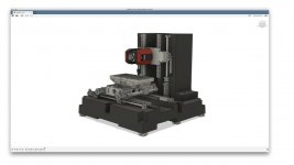
I am quite familiar with Fusion 360. Here is a balanced 6-axis omnidirectional machining center (first of its kind, most machines only have 5 axes) that I designed with it last Summer. I have a love-hate relationship with that particular piece of software. Ultimately, I want to learn SolidWorks and Catia, because this is what one needs to design really complex things. But I am a quarter French, so I might be biased there... 😉
I agree with you that this could be done, but I'm not really trying to keep the BOM at a manageable level for the time being. Instead, I am trying to prove the overall concept for a multi-level modular system, and part of this proof will come from the level of finish that we can offer.
For example, here is a product that I got some inspiration from. I have not seen the product myself, but I am under the impression that the build quality is not that great, and this is certainly not something that a professional would use. This is more like a toy. The original idea is interesting, but it needs further development.
What the OTO project brings to the table is two levels of modularity: multiple plates on a tray and multiple bricks on a plate. By doing so, we can have two different types of interconnect (USB and OTOBUS™), and this will allow us to develop really interesting blocks (like the AK4499EQ-powered DAC block). But if we go down that path, we want to make sure that the bricks have a matching level of quality (it would be a shame to wrap such a great IC into a sub-par shell). And that is why I am spending so much time trying to make the form factor work.
Once we prove that it is possible, we can then review the design and improve many things that will cut the BOM in half or even more. But trying to do everything all at once would be the best way to deliver nothing of value in the end.
But I'm sure I'm preaching to the choir here...
Attachments
Last edited:
LED Board for P4 Brick
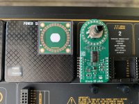
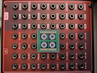
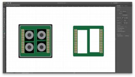
Yesterday, I posted this picture of the LED board that will be installed within the P4 brick, directly mounted on top of the base board and underneath the top cover board. This board has 4 sets of 5 WS2812C-2020 serially-controlled LEDs. The board is shown on its own on the right, and mounted on top of the base board with four TRS ports on the left.
Now, if this was not already obvious, I should point out that this middle PCB will wrap around the four vertically-mounted TRS connectors. And because the WS2812C-2020 is running on 800kHz, this might create some unwanted interference. Therefore, I am planning to split the LED board into two separate sections that will be isolated from each other. Therefore, since the WS2812C-2020 needs four circuits (VDD, GND, IN, OUT), we will use two sets of two 2.54mm headers, with one pair for each side of the board. That way, the board will stand on top of four dual-circuit headers (one on each corner) and no high-frequency current should wrap around the TRS connector.
Granted, these ports will be used for modular audio synthesis, which really does not need any kind of Hi-Fi treatment. Nevertheless, we'll still try to follow some best practices. And if there are other things that we can do to make things even better, please let me know.
Of course, we could use regular LEDs, but these would require a dedicated IC for driving them, and twenty is not a good number for RGB LEDs (most drivers go up to 48 channels, which means 16 LEDs), and 5 levels are a lot better than 4 (subjectively speaking, a lot better than 25%, because it gives you three normal blue/green levels, one orange, and one red).
Attachments
Last edited:
I am not a 3D printing expert, and I know it's hard to create clear objects via FDM printing and typical PLA and ABS filament, but you might be able to sketch something up in Fusion 360 or Solidworks and get it printed if you are willing to sand or acetone finish it by hand. Of course, it's more work and another app to learn if you haven't used them before. I think Fusion 360 has a free version.
Also, question 18 on this FAQ is interesting:
18. Can I cut the light pipe myself?
Adjusting the length of a light pipe by anyone other than the manufacturer is not recommended.
Cutting the light pipe will change the optical characteristics, making it less effective in the device it was specified for. Any bubbles or scratches in the light pipe will ruin transference, as light will not be directed where it was intended.
In other words, creating light pipes with 3D printing is unlikely to yield great results if we want to ensure that we have a consistent level of light transference across all LEDs. And for a semi-continuous indicator like a LED ring or a bargraph, this is a pretty big deal.
I should also point out that using rotary encoders instead of potentiometers for applications like music synthesis is a big bet in and by itself. If the user experience is not great, musicians simply won't use them. For example, the detent on the Alps encoder used by the Knob G Click feels terrible. In contrast, some Bourns encoders that I played with four years ago were much better, and I have high expectations for the optical encoders that I just ordered from CUI and CTS.
As far as the LED rings are concerned, they will need to be finely tuned for them to work. For example, the luminosity level needs to be right so that they are not tiring to look at (of course, this should be easy to set with software thanks to PWM). And I am convinced that having 32 LEDs instead of 24 and having a matching number of detents on the encoder will make a huge difference. One of the many reasons that rotary encoders with LED rings are not more prevalent on contemporary products is that short of running that extra mile, they simply do not work from a user experience standpoint (not to mention the total BOM cost, which is in the $50 to $75 range for a single encoder brick).
Last edited:
CFAL12836A0-088
We just found the perfect component for the bricks that have a small display and two controls:
- D1B2: One small display and two buttons
- D1E2: One small display and two small encoders
- D1P2: One small display and two audio/control ports
- D1S2: One small display and two switches
The CFAL12836A0-088 from Crystalfontz. With dimensions of only 26.59mm × 13mm, it will take less than half the size of the brick, leaving the other half for the controls and some mounting hardware. And because it comes with a long FPC connector, we will be able to mount the matching Molex 501912-3390 on the base board directly, without any PCB in between.
Now, we need to find the right mounting hardware for it.
OTOBUS™ Pinout
This sheet outlines a first pinout for our OTOBUS™ interconnect, using only one of the two 30-circuit ER8 connectors that each OTO brick will have. This should be plenty for getting us started. The pins of the second connector will be left unconnected initially. Down the road, we'll decide whether we mirror the pins, or whether we add new pins. But if we do the latter, we'll have to make the interconnect foolproof with some additional mechanical component.
This sheet outlines a first pinout for our OTOBUS™ interconnect, using only one of the two 30-circuit ER8 connectors that each OTO brick will have. This should be plenty for getting us started. The pins of the second connector will be left unconnected initially. Down the road, we'll decide whether we mirror the pins, or whether we add new pins. But if we do the latter, we'll have to make the interconnect foolproof with some additional mechanical component.
Also, question 18 on this FAQ is interesting:
In other words, creating light pipes with 3D printing is unlikely to yield great results if we want to ensure that we have a consistent level of light transference across all LEDs. And for a semi-continuous indicator like a LED ring or a bargraph, this is a pretty big deal.
I should also point out that using rotary encoders instead of potentiometers for applications like music synthesis is a big bet in and by itself. If the user experience is not great, musicians simply won't use them. For example, the detent on the Alps encoder used by the Knob G Click feels terrible. In contrast, some Bourns encoders that I played with four years ago were much better, and I have high expectations for the optical encoders that I just ordered from CUI and CTS.
As far as the LED rings are concerned, they will need to be finely tuned for them to work. For example, the luminosity level needs to be right so that they are not tiring to look at (of course, this should be easy to set with software thanks to PWM). And I am convinced that having 32 LEDs instead of 24 and having a matching number of detents on the encoder will make a huge difference. One of the many reasons that rotary encoders with LED rings are not more prevalent on contemporary products is that short of running that extra mile, they simply do not work from a user experience standpoint (not to mention the total BOM cost, which is in the $50 to $75 range for a single encoder brick).
Do you need to store settings for switching between different inputs (i.e. do you have to "control" the virtual knob position)?
If not, an alternative to a rotary encoder if you need smooth feel is to use a cheap linear pot off a rail into a MCU ADC and read the value.
- Home
- Source & Line
- Digital Line Level
- 8 × AK5578EN + 8 × AK4499EQ ADC/DAC Boards