OTOBUS
Here is a first outline of the new OTOBUS™ (pun intented). With full support for I²S, 12V (for Eurorack), and a spare pin, we need 24 circuits. Now, we need to find a connector (or pair of connectors preferably) that could give us that, with the ability to mix and match different pairs of receptacles and plugs in order to get different mating height, like we had with the Hirose ER8 (7.15mm, 9.15mm, 10.15mm, and 12.15mm). And the connectors we pick should offer at least 100 mating cycles of durability and should not be too expensive (I love some of the Samtec connectors, but at $10 a piece, they're not a viable option).
Here is a first outline of the new OTOBUS™ (pun intented). With full support for I²S, 12V (for Eurorack), and a spare pin, we need 24 circuits. Now, we need to find a connector (or pair of connectors preferably) that could give us that, with the ability to mix and match different pairs of receptacles and plugs in order to get different mating height, like we had with the Hirose ER8 (7.15mm, 9.15mm, 10.15mm, and 12.15mm). And the connectors we pick should offer at least 100 mating cycles of durability and should not be too expensive (I love some of the Samtec connectors, but at $10 a piece, they're not a viable option).
Last edited:
Here is a first outline of the new OTOBUS™ (pun intented). With full support for I²S, 12V (for Eurorack), and a spare pin, we need 24 circuits. Now, we need to find a connector (or pair of connectors preferably) that could give us that, with the ability to mix and match different pairs of receptacles and plugs in order to get different mating height, like we had with the Hirose ER8 (7.15mm, 9.15mm, 10.15mm, and 12.15mm). And the connectors we pick should offer at least 100 mating cycles of durability and should not be too expensive (I love some of the Samtec connectors, but at $10 a piece, they're not a viable option).
If we get rid of the multiplexed data line for upload of the I²S bus and keep a single GND pin for the entire bus, we can fit everything within 20 pins, which would be perfect for a Samtec ERF5/ERM5 or Hirose ER8.
Thoughts?
ERF8/ERM8 Connectors
So far, the best option that we have found is the ERF8/ERM8 connector series. It is available with 13 positions (26 circuits), which means that we could add back the I²S Multiplexed Data Line, one ground circuit per voltage level, and three unconnected circuits for future additions (Cf. OTOBUS™). It is available with many different mating heights (7, 9, 10, 11, 12, 13, 14, 15, 16, 17, and 18mm), and it is part of the Extended Life Products family, which means that it supports 250 to 2,500 cycles. Finally, it is dual sourced by Hirose, which makes it a reliable long-term option. At $2.73 for the female version, it is not cheap, but it should do the job.
So far, the best option that we have found is the ERF8/ERM8 connector series. It is available with 13 positions (26 circuits), which means that we could add back the I²S Multiplexed Data Line, one ground circuit per voltage level, and three unconnected circuits for future additions (Cf. OTOBUS™). It is available with many different mating heights (7, 9, 10, 11, 12, 13, 14, 15, 16, 17, and 18mm), and it is part of the Extended Life Products family, which means that it supports 250 to 2,500 cycles. Finally, it is dual sourced by Hirose, which makes it a reliable long-term option. At $2.73 for the female version, it is not cheap, but it should do the job.
Similar Project
Here is a similar project building an open source LED ring for rotary encoder. What's interesting about it is that they are using the WS2812C-2020 intelligent control LED. These LEDs do not require any driver, which makes the circuit a lot simpler. Their 2022 package would probably prevent us from putting 32 on the board, but 24 might be doable. What's clear is that we will definitely use these for the bargraphs of our motorized faders.
Here is a similar project building an open source LED ring for rotary encoder. What's interesting about it is that they are using the WS2812C-2020 intelligent control LED. These LEDs do not require any driver, which makes the circuit a lot simpler. Their 2022 package would probably prevent us from putting 32 on the board, but 24 might be doable. What's clear is that we will definitely use these for the bargraphs of our motorized faders.
Last edited:
Here is a similar project building an open source LED ring for rotary encoder. What's interesting about it is that they are using the WS2812C-2020 intelligent control LED. These LEDs do not require any driver, which makes the circuit a lot simpler. Their 2022 package would probably prevent us from putting 32 on the board, but 24 might be doable. What's clear is that we will definitely use these for the bargraphs of our motorized faders.
Here is the proper link to the WS2812C-2020.
Here is a similar project building an open source LED ring for rotary encoder. What's interesting about it is that they are using the WS2812C-2020 intelligent control LED. These LEDs do not require any driver, which makes the circuit a lot simpler. Their 2022 package would probably prevent us from putting 32 on the board, but 24 might be doable. What's clear is that we will definitely use these for the bargraphs of our motorized faders.
Good news: the APA-104-1515 is similar but comes in a 1515 package that will definitely fit on our board. With this approach, the connector between the encoder board and the LED board just needs four circuits: VCC, GND, IN, and OUT. So here we go: 32 RGB LEDs for our rotary encoder. In retrospect, I am pretty happy that the original plan did not work out...
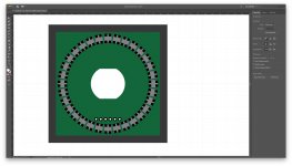
RGB LED Ring
Here is an outline of the LED ring with 32 × WS2812C-2020 RGB LEDs. Surprisingly, the 2022 package has a smaller footprint than the 1515, so we will stick with it. The ring has a 27mm diamater, which will fit comfortably on our 28mm × 28mm board. Each LED needs a 100nF capacitor, which will be placed on an inner ring, and we should not have any problems making them fit either.
As far as I can tell, this should work...
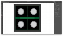
As a sidenote, this pattern creates a nice optical illusion making the rectangles look like trapezoids...
Here is an outline of the LED ring with 32 × WS2812C-2020 RGB LEDs. Surprisingly, the 2022 package has a smaller footprint than the 1515, so we will stick with it. The ring has a 27mm diamater, which will fit comfortably on our 28mm × 28mm board. Each LED needs a 100nF capacitor, which will be placed on an inner ring, and we should not have any problems making them fit either.
As far as I can tell, this should work...
As a sidenote, this pattern creates a nice optical illusion making the rectangles look like trapezoids...
Attachments

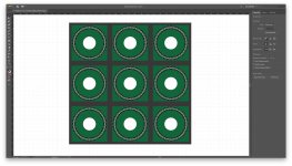
9 E1 Bricks on a Plate
Here is another interesting sketch: this one shows 9 × E1 bricks on a 96mm × 96mm plate. The boards are 28mm × 28mm and the bricks are 32mm × 32mm. This sketch demonstrates that the rings will not be too close to each other. Also, the round holes have a 10mm diameter and will let the shaft of the encoders through. This shows that we will be able to use this brick with knobs that have a 20mm diameter (in fact 22 or 23mm would still work). And this layout still leaves plenty of space in the corner for conventional fastening hardware.
Here is another interesting sketch: this one shows 9 × E1 bricks on a 96mm × 96mm plate. The boards are 28mm × 28mm and the bricks are 32mm × 32mm. This sketch demonstrates that the rings will not be too close to each other. Also, the round holes have a 10mm diameter and will let the shaft of the encoders through. This shows that we will be able to use this brick with knobs that have a 20mm diameter (in fact 22 or 23mm would still work). And this layout still leaves plenty of space in the corner for conventional fastening hardware.
Attachments
Connector Pairs
In order to mount two boards on top of each other, two connectors are usually better than one from a mechanical standpoint, and this is something that I have been struggling with for most of the day yesterday, looking for connectors with less circuits than the one we have selected (ERF8 with 26 circuits), but with a smaller footprint so that we could put two on the brick's encoder board. This search was made even more difficult by the requirement to have different mating heights. And to make a long story short, we came back empty handed.
But an alternative option exists and is becoming more and more attractive: using separate connectors for signal and power. It looks like it could have been possible with the Samtec mPOWER connectors, which are designed to work in combination with many other Samtec connectors, including the ERF8/ERM8. With that approach, the encoder board (or any base board for any brick) would have an ERM8 and an UMPS connector on the bottom, matching ERF8 and UMPT connectors on the plate (where 9 bricks can be connected).
Unfortunately, this option will not work, because the UMPS and UMPT connectors do not have the same mating strategy as the one offered by the ERF8 and ERM8. For the former, each connector comes in two heights, providing 4 different mating heights. For the latter, the ERF8 comes in three heights, while the ERM8 comes in four heights. But because a plate won't know which bricks will be mounted on it, the connectors offered by the plate must be the smallest ones (5mm), while only the bricks will use connectors of different heights (2mm, 5mm, 8mm, or 9mm for ERM8). In other words, pairs of ERF8/ERM8 connectors give us 4 different mating heights from 7mm to 14mm, while pairs of UMPS and UMPT connectors give us only 2 (5mm and 10mm).
Bottomline, one last solution remains: using two ERM8 connectors on the brick and two ERF8 connectors per brick on the plate. One would have 10 positions (20 circuits) and would be used for signals, while the other would have 5 positions (10 circuits) and would be used for power. This arrangement is described on this sheet.
This approach has many benefits:
- Very stable mechanical assembly.
- Foolproof assembly (the two connectors have different sizes).
- Clean separation of circuits (signal on one side, power on the other).
- Dual rail 12V DC on the power connector (similar to Eurorack).
- One spare circuit on the power connector for future developments.
- Two spare circuits on the signal connector for future developments.
- High durability (250 to 2,500 mating/unmating cycles)
Of course, that also means an increase of the BOM, with about $10 allocated to the connectors. This is a lot of money for connecting something that might have a single button on it, but it becomes more reasonable when the brick as a rotary encoder with 32 RGB LEDs, 4 Audio/CV ports, or a high-resolution OLED display. Most importantly, this will guarantee a great user experience, which is by far our #1 priority.
Another downside is the space used on the bottom of the brick's base board, but the analysis of all our bricks shows that it should not be a problem, because we can stack multiple boards within the brick itself (three in the case of the E1 brick). And even on the bottom side of the base board, we will have 28mm × 18mm to play with, plus 9mm on the left and right sides of the power connector, which is 10mm long.
Conclusion: we will go down that path for the time being.
Last edited:
Brick Stack
What makes the design of a generic system for modular user interfaces so challenging is that user interface components have different height requirements. For example, our rotary encoders have a 5mm-tall base, but our TRS connectors have a 10mm-tall base. Therefore, whatever comes on top of them must come at different heights, and with the former we will have two boards coming on top of the encoder (the LED board and the top cover board), while we will have only one for the latter (the top cover board). But the top cover board for the encoder brick won't have any component on it, while the top cover board for the Audio/CV brick will have some reverse-mounted LEDs (with through holes in the PCB). All these constraints conspire to create a really difficult puzzle to solve.
What is becoming apparent is that we probably won't standardize the interconnects between boards within bricks, because the range of options is simply too large. And while some bricks might propagate the OTOBUS™ from one board to another, most won't. For example, the LED board of the E1 board only requires four circuits, and it would be a massive waste to use two pairs of ERF8/ERM8 connectors just for that...
Yet another challenge is purely mechanical: some bricks have components that could be used for securing one board on top of the other (the Audio/CV brick for example, where the 4 TRS connectors can serve as mounting posts), while others do not (the single-button brick or single-encoder brick for example). Therefore, we will probably have to develop specific strategies for different bricks, which is not as satisfying as having a generic system...
Open Parts Library
For simple parts like capacitors and resistors, we will try to select components that are available on the ShenZhen Open Parts Library. This should make the assembly of our prototypes both cheaper and faster.
For simple parts like capacitors and resistors, we will try to select components that are available on the ShenZhen Open Parts Library. This should make the assembly of our prototypes both cheaper and faster.
Better Rotary Encoder
Now that we have 32 LEDs on our ring, we might want to consider having a rotary encoder with 32 detents per 360° rotation, and a matching resolution. Unfortunately, most encoders will either provide 24 or 30 detents, which could be quite confusing for the end-user.
Fortunately, there is the C14D32P-A3, which offers 32 detents and 32 pulses per revolution. Not only that, but its form factor is really interesting. The picture shows the C14D32P-D3 with what they call Header II (Cf. datasheet on page 5/7), but the C14D32P-A3 does not come with any header. Instead, it comes with 0.5mm through holes, on which any header can be mounted. What this means is that we could merge back two boards into one, having the encoder directly soldered onto the LED board. Therefore, our E1 brick would have just two boards: the base board with encoder and LEDs and the top cover board. And that means that we would not have to look for a connector with just four positions to connect the encoder board to the LED board, because there would be a single board instead of two.
I like that solution, a lot...
Attachments
Last edited:
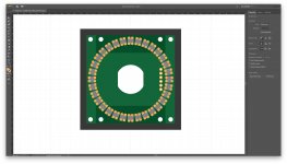
Encoder on board
Here is how everything would fit on the board. Again, it's a tight fit, but it seems like it's going to work...
Note: I'm doing all these sketches in Adobe Illustrator, because it's a lot faster than creating all the footprints for components that we might not need in the end.
Here is how everything would fit on the board. Again, it's a tight fit, but it seems like it's going to work...
Note: I'm doing all these sketches in Adobe Illustrator, because it's a lot faster than creating all the footprints for components that we might not need in the end.
Attachments
OTOBUS™ Connectors
We found another problem with the latest design: the through holes for the indexing pins of the ERM8 connectors interfere with the LEDs...
Conclusion, we need to use wider connectors. But the smallest that will fit is the ERM8-020 with 20 positions and 40 circuits, which means that if we put two of them on every brick, we get 80 circuits, while we needed only 20 to 24. The attached sketch shows what it would look like, including 4 × 1.45mm through holes for M1.4 screws.
If we were to go down that path, we would have three options:
1. Use 40 circuits only but mirror the connectors so that bricks can be rotated.
2. Use 80 circuits and prevent brick rotation.
3. Use about 60 to 70 circuits while still allowing brick rotation.
Options #1 and #3 are quite attractive, because the ERF8/ERM8 connectors are not symmetrical, and their indexing pins are offset from the longitudinal center line. Therefore, the ERM8 connectors have to be mounted on the board in a symmetrical manner, or their through holes will interfere with the LEDs of the E1 brick. As a result, if we wanted to implement option #2, we'd have to add some mechanical component that would prevent incorrect insertion.
So we'll go for option #3.
This approach opens up many more possibilities: by exposing 60 to 70 circuits of our STM32H743 MCU to each and every brick, we get a lot of interfaces directly, without requiring any kind of multiplexing on the bricks. Of course, it will make the specification of our OTOBUS™ interconnect a lot more complex, but this seems to be the best option that we have so far...
Attachments
Last edited:
Back to Hirose
After many iterations, here is a configuration that I am starting to really like. We replaced the Samtec ERM8 connector by a Hirose ER8. While the two series are compatible, they come in different sizes, and the Hirose has the benefit of offering a 30-position (30 circuits) version. This is all a bit confusing, because Samtec and Hirose do not have a consistent terminology for "positions": in Samtec's case, if you have p positions and r rows, you have p × r circuits, while in Hirose's case, you simply have p circuits. In other words, positions and circuits are synonymous for Hirose, but not for Samtec.
In any case, Samtec does not offer any 15-position/30-circuit connectors, while Hirose does. The benefits of going for such a connector are:
- Closer to the number of circuits that we really need
- Smaller footprint on the board
- Lower BOM costs
- More space for mounting hardware
The last benefit is the most critical one. As discussed earlier, we are planning to use the PEM ReelFast surface mount nuts and spacers/standoffs (Cf. datasheet page 4). Unfortunately, the minimum solder pad diameter is 4.19mm (be it for M1, M1.2, M1.4, or M1.6). As a result, these pads did not fit with the 40-circuit Samtec connector, but they do with the 30-circuit Hirose alternative. And that will allow us to use M1.6 mounting hardware, which is quite a bit more common than M1.4.
The only drawback is that we are now limited to only two mating heights: 7.15mm and 10.15mm. Now, this might not be too much of a problem, because 10.15mm are what we need for both the single encoder brick and the Audio/CV brick, as well as most bricks that have simple controls like buttons and switches.
So, all in all, it's looking pretty good, but that sure was not easy...
Attachments
Last edited:
P4 Brick
As a proof of concept, here is a sketch for the P4 brick made of 4 Audio/CV ports, using the Kobiconn 161-MJ355W-EX TRS connector. The connectors must be offset in relation to each other if we want to preserve a regular pattern on the top cover, because they are not symmetrical, and because we can make them overlap the underlying Hirose connectors a little bit without their through holes interfering with the soldering pads of the Hirose connectors. Nevertheless, this goes to show that they would fit within our planned form factor. That being said, I really wish that we could space them apart a bit more in order to get a more regular pattern when multiple such bricks are used on a plate. With the current arrangement, the TRS connectors will be clustered in groups of four that might or might not reflect any logical arrangement with respect to the instrument that they are supposed to be part of. In fact, this is probably not good enough, but for the time being, it will do...
As a proof of concept, here is a sketch for the P4 brick made of 4 Audio/CV ports, using the Kobiconn 161-MJ355W-EX TRS connector. The connectors must be offset in relation to each other if we want to preserve a regular pattern on the top cover, because they are not symmetrical, and because we can make them overlap the underlying Hirose connectors a little bit without their through holes interfering with the soldering pads of the Hirose connectors. Nevertheless, this goes to show that they would fit within our planned form factor. That being said, I really wish that we could space them apart a bit more in order to get a more regular pattern when multiple such bricks are used on a plate. With the current arrangement, the TRS connectors will be clustered in groups of four that might or might not reflect any logical arrangement with respect to the instrument that they are supposed to be part of. In fact, this is probably not good enough, but for the time being, it will do...
Attachments
Last edited:
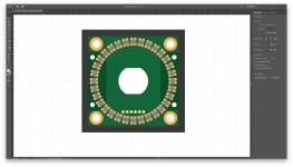
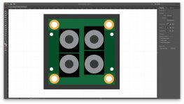
E4 Brick
This one is quite interesting as well. It shows a sketch for the E4 brick, which is made of 4 × 291V1022F832AB rotary encoders. These were selected because they are really small and expose all their pins on one side, yet provide 32 detents. What this shows is that they will fit, but they will obstruct the through hole for fastening hardware, and they won't leave any room for any components on the top cover (but none were required so far). In fact, there is probably enough room on the bottom side of the board to put the debouncing circuits and Schmitt triggers that were on the original design. Also, the current arrangement is almost perfectly regular, in the sense that encoders would be spaced almost evenly if multiple such bricks were to be mounted on a single plate. In fact, we could make this layout perfect if we were to go from 28mm × 28mm to 29mm × 29mm for the PCB dimensions. This extra mm would make the walls of our frames 0.5mm thinner, but it could add quite a bit of flexibility for many high-density bricks (increasing the diameter of the LED ring on E1 by 1mm for example).
What I should mention as well is that the encoders used for the E1 and E4 are now optical encoders, instead of the mechanical encoders that we were planning to use originally. These are quite a bit more more expensive (about $20 a piece for 1, $10 when buying 1K), but durability goes from 150,000 cycles to 1,000,000 cycles. And I also expect their mechanical feel to be subjectively better, but this will be tested this week by ordering some sample parts.
Attachments
Last edited:
Aluminum Wall Thickness
Here is an interesting article about the minimum thickness of walls in aluminum profiles. 0.050" seems to be fine, which means that 1.25mm should work. If we were to do that for our 32mm × 32mm bricks, it would allow us to have 29mm × 29mm boards, while preserving a 0.25mm gap all around.
I think we'll go for that.
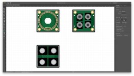
29mm × 29mm Boards
Here are what the boards look like at 29mm × 29mm. With this resizing, the E1 board looks a lot more manageable, while the E4 brick offers a perfect layout. Now I need to find better TRS jacks that would give us a perfect layout for P4 as well.
Here are what the boards look like at 29mm × 29mm. With this resizing, the E1 board looks a lot more manageable, while the E4 brick offers a perfect layout. Now I need to find better TRS jacks that would give us a perfect layout for P4 as well.
Attachments
OLED Switch Click
Mikroe just released the OLED Switch Click built around the NKK Switch ISC15ANP4. We will give it a try.
Mikroe just released the OLED Switch Click built around the NKK Switch ISC15ANP4. We will give it a try.
Attachments

- Home
- Source & Line
- Digital Line Level
- 8 × AK5578EN + 8 × AK4499EQ ADC/DAC Boards