This is a transformer datasheet rather than a full amp application note. For a moment, I thought I would have to explain a full OPA LN application under Guru Wurcer's fiercely pedantic and eagle eye 😱Here's a chance to clarify, please take this Jensen applications note and explain where the 1.5dB NF comes from.
https://www.jensen-transformers.com/wp-content/uploads/2014/08/jt-115K-e1.pdf
________________
The most important spec for this transformer isn't specified in da datasheet but only implied. The transformer is designed for 150R microphones and this is represented by their 2x75R in TEST CIRCUIT 1 & 2. This affects practically all aspects of its design & performance.
A transformer N x Voltage step up ratio also steps up Impedances by N^2 x
We can transform every Impedance on the primary side to the secondary side by N^2. In our case, the voltage step up is 10x so we step up impedances by 10^2 = 100.
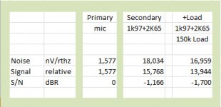
The primary side has Rs + DC resistance = 150R + 19R7 and this is multiplied by 100x to give 15K + 1k97 equivalent on the secondary side.
The secondary also has 2K65 DC resistance so we see 15K 'active' generator resistance and 1K97 + 2K65 = 4K62 evil parasitic transformer losses on the secondary. (Iron losses are very small for LN transformers like these so just looking at resistive Cu losses is good. You need to consider the 'iron' for LF. Good transformer design also attempts to share the losses on both primary & secondary (ie transformed 'DC should be the same on both primary & secondary) .. but this is often kiboshed by existing wire sizes.)
Because only the generates 15K generates signal, the transformer has lost 15K / (4k62 + 15K) = 0.7645 which is 10log(0.7645) = -1.166dB S/N cos the parasitic resistance of the windings.
But ignoring the following LNA, this feeds their 150K resistor which is a potential divider of 150K / (15K + 4k62 + 150K) = 0.884 which is -0.533dB.
So the transformer causes a S/N loss of 1.166 + 0.533 = 1.699dB which I hope Guru Wurcer will pass for someone hu kunt reed rite en kunt 😱
The 150K isn't needed to bias a FET i/p LNA or valve but is just there to damp da ultrasonic HF resonance. You can recover 0.533dB S/N by replacing it with a Zobel that doesn't put any load on the transformer at audio.
Then the FET i/p LNA amp itself will contribute a further reduction in S/N and increase in NF. Perhaps a better definition of NF might be the reduction in S/N of a device for a resistive source .. be it a passive transformer or an active amp.
This is another practical obstacle to achieving nearly 0dB NF with Guru Wurcer's FET i/p LNA. Once you start looking at the transformers, you find you can't avoid losing a dB or so in practical transformer windings. That's on top of the Black Magic HF problems. I'll deal with the LF stuff later.
Last edited:
Richard, I don't have models for any MC SUT's but I did run some simulations with some Edcore interstage transformers and found that they ran about 0.5dB "NF" when unloaded driving an ultra low noise FET amp. Did you look at that Jensen app note, ironically it uses my AD743 "DA LOWEST NOISE IC FET OP-AMP IN DA UNIVERSE". I can only figure that they included the op-amp and termination in the noise. Big smilies all around 🙂.
Is there a reason why there are no FET CFB op amps?
OK, there is some asymmetry, but with CFB that exists anyway, and if we want
only high input impedance and low noise we could do everything in bipolar but
the ninv. FET input. That might bring us to 1.x nV/rtHz land.
Is there a reason why there are no FET CFB op amps?
There are no serious complementary JFET processes, and IIRC the biasing for depletion mode devices gets strange. I have no idea about CMOS and there might be some out there. There is also the low gm, reducing any benefit, I could probably come up with more reasons.
There are no serious complementary JFET processes, and IIRC the biasing for depletion mode devices gets strange. I have no idea about CMOS and there might be some out there. There is also the low gm, reducing any benefit, I could probably come up with more reasons.
CMOS CFB op amps do exist, at least as analog cell building blocks, I've seen them myself. But as you say, due to the low transconductance they are not practical for any stand alone application, nobody needs an op amp able to charge a maximum 0.5pF output load 😀. cmos is also rather noisy (getting much better in the last years, but still away from bipolar/jfet) so except for the chopper versions with no 1/f noise there's no way out.
This is a transformer datasheet rather than a full amp application note. For a moment, I thought I would have to explain a full OPA LN application under Guru Wurcer's fiercely pedantic and eagle eye 😱
Thanks, a whole bunch of little things add up, the devil is in the details that's what engineering is all about.
Because only the generates 15K generates signal, the transformer has lost 15K / (4k62 + 15K) = 0.7645 which is 10log(0.7645) = -1.166dB S/N cos the parasitic resistance of the windings.
But ignoring the following LNA, this feeds their 150K resistor which is a potential divider of 150K / (15K + 4k62 + 150K) = 0.884 which is -0.533dB.
So the transformer causes a S/N loss of 1.166 + 0.533 = 1.699dB which I hope Guru Wurcer will pass for someone hu kunt reed rite en kunt 😱
0.7645 and 0.884 above are voltage ratio, why are you then taking 10log() to get to dB? 10log() is for power, or V^2 ratios. S/N is by definition a power ratio so using a voltage ratio to get the S/N is incorrect?
Last edited:
Yes. In fact my M-audio DMP3 + string + sealing wax special beats that easily and it doesn't use transformers. The really worthwhile gain is replacing the 4038's internal transformer with zillion ZTX/mA Duraglit.1.7dB ref. 300ohm is by your own arithmetic 1.74nV/rtHz (300 ohm has 2.2nV/rtHz), nothing to call home about, actually not something that qualifies as true "low noise". So you are likely including here an unspecified transformer gain.
I don't spurn the use of En/In. In fact my little list of LN devices has columns for both .. as well as Ropt = En/In and NF at that source resistance. I need En & In to determine both Ropt & NF too.I don't suggest you to switch to the En/In noise metric (like everybody in this century) but just to illustrate how the numbers you are throwing around are confusing, due to unspecified side conditions (reference resistance, transformer gains, etc...).
I'm not urging anyone to switch to NF for Life, the Universe & everything. Just suggesting that it is useful to tell us if we are close enough in any LN application. Most mere mortals can't conjure up Rnv & Rni for En & In or vice versa without the aid of an abacus 🙂
Not saying that it matters, anyway, only that there's a large population out there that will freak about 100uA current through the cartridge.
The input impedance of the Duraglit (and #375 as well) is about 1/2gm that is (for Ic=2.5mA) about 5ohm so yes, it is reading a regular MC (Rs=10...20ohm) almost in short.
When Dynavector introduced the DV23R and DV17D cartridges they also offered an active preamp which was, at least for my knowledge, the first commercial MC preamp with a virtual ground input (= current input). This preamp got some very good reviews in the HiFi press. If I remember correctly they wondered why the sound was not dull or muddy as they would have expected due to common beliefs. And there are many more such amps from well known brands available today and almost all get good reviews.
So Dynavector at least recommended this mode of operation not fearing such evil currents in the cartridge - and they should know.
Last edited:
That's not surprising if these interstage transformers are bigger than the input transformers. A bigger core allowsRichard, I don't have models for any MC SUT's but I did run some simulations with some Edcore interstage transformers and found that they ran about 0.5dB "NF" when unloaded driving an ultra low noise FET amp.
- Less turns for a given LF performance
- More space so you can use thicker Cu wire
- Both these are beneficial for noise
This isn't a good transformer but it illustrates clearly what happens when you use a transformer far from its designed resistance. Something similar happens on ALL transformers .. just the numbers are different. At the risk of generalising, you only need to terminate one of the windings with the 'design' resistance to get the design LF response/overload performance
If you are prepared to forgo some LF performance, the gains in noise performance are great cos less turns & thicker Cu wire too.
But there are other tricks you can pull. The core/turns/flux in a transformer is required to support LF voltage. If you arrange that the voltage across the transformer is always small, you can get away with a smaller core and/or less turns & thicker wire giving you less noise/THD bla bla
You do this if your transformer feeds a Virtual Earth. GG Baxandall did this for a number successful commercial designs.
IMHO, Virtual Earth is unfairly overlooked for LN. In fact, cos you avoid EVIL resistors in the signal path, it is often better than non-inverting. Only the charge amp brigade (like Guru Wurcer's Linear Audio offerings) seem to take advantage of this.
Attachments
Because only the 15K generates signal, the transformer has lost 15K / (4k62 + 15K) = 0.7645 which is 10log(0.7645) = -1.166dB S/N cos the parasitic resistance of the windings.
But ignoring the following LNA, this feeds their 150K resistor which is a potential divider of 150K / (15K + 4k62 + 150K) = 0.884 which is -0.533dB.
So the transformer causes a S/N loss of 1.166 + 0.533 = 1.699dB which I hope Guru Wurcer will pass for someone hu kunt reed rite en kunt 😱
Mea culpa, mea culpa, mea maxima culpa! My excuse is that this is a beach bum's pre-morning coffee effort. It is only half right.0.7645 and 0.884 above are voltage ratio, why are you then taking 10log() to get to dB? 10log() is for power, or V^2 ratios. S/N is by definition a power ratio so using a voltage ratio to get the S/N is incorrect?
"15K / (4k62 + 15K) = 0.7645 which is 10log(0.7645) = -1.166dB S/N" is correct. It is just the ratio of resistors and we are looking at noise contributions. It's the same process that determines doubling resistance increases voltage noise by 3dB.
"150K / (15K + 4K62 + 150K) = 0.884 which is -0.533dB" is wrong. Here we are looking at loss of signal voltage so it should be 20log(0.884) = -1.07dB S/N
So the Jensen transformer causes a S/N loss of either -1.166dB or -2.236dB (NF of either 1.166dB or 2.236dB) depending on whether you use a Zobel or an EVIL 150K resistor. Please don't hit me for being so far from the Jensen spec, Guru Wurcer.😱
__________________
To underline Guru Wurcer's point about LN FET i/p amps. ... His AD745 has a guaranteed Env of 4nV/rt(Hz) which is Rnv of 1K. In the Jensen datasheet, this, with the 15K + 4K62 it sees, adds (15K + 4K62 + 1K) / (15K + 4K62) = 1.051 and 10log(1.051) = 0.216dB NF to the above. 😱 10log cos we are dealing with noise resistances.
The noise performance is almost all due to the transformer. and its EVIL resistances. If you are unhappy with that, you can recover most of the AD745's 0.216dB S/N degradation by rewinding the transformer so its secondary presents the AD745 with its Ropt of 450K 😀
__________________________
BTW, I hope most of you understand that my transformer examples are only to highlight the fact that for LoZ LN, even the best transformer/amp designs are likely to fall short of the zillion ZTX/mA Duraglit variants. Eric & I have yet to prove this in practice and our comparison will be with Les Watt's active ribbon which uses a transformer that maximises the advantages of LN FET i/p
Also my Jurassic 1.7dB NF 200R Calrec effort was with full P48 and protection for P48 & RFI ... details that aren't trivial .. some of which are helped and others hindered by transformers.
Last edited:
Richard,Mea culpa, mea culpa, mea maxima culpa! My excuse is that this is a beach bum's pre-morning coffee effort. It is only half right.
"15K / (4k62 + 15K) = 0.7645 which is 10log(0.7645) = -1.166dB S/N" is correct. It is just the ratio of resistors and we are looking at noise contributions. It's the same process that determines doubling resistance increases voltage noise by 3dB.
"150K / (15K + 4K62 + 150K) = 0.884 which is -0.533dB" is wrong. Here we are looking at loss of signal voltage so it should be 20log(0.884) = -1.07dB S/N
So the Jensen transformer causes a S/N loss of either -1.166dB or -2.236dB (NF of either 1.166dB or 2.236dB) depending on whether you use a Zobel or an EVIL 150K resistor. Please don't hit me for being so far from the Jensen spec, Guru Wurcer.😱
Your original calculation was correct, because the 150K load is not only attenuating the signal, but also the noise. See below.
Hans
Attachments
Cmos is getting better and better .I have no idea about CMOS and there might be some out there.
There is this device from Rohm with the same noise as the AD743, 5uv offset and 1mA quiescent current.
https://www.rohm.com/datasheet/LMR1802G-LB/lmr1802g-lb-e
Then there is a slightly lesser version from TI, the OPA1656
http://www.ti.com/lit/ds/sbos901a/sbos901a.pdf
Hans
Cmos is getting better and better .
I know but the question was about CFA's. There's also a 1fA CMOS electrometer out there somewhere.
Richard,
Your original calculation was correct, because the 150K load is not only attenuating the signal, but also the noise.
See below.
This is still mix and match. When you use an ideal or near ideal voltage amplifier you want SNR in dBV not dBW. Taking 10*log of a simple voltage divider ratio just makes for unnecessary interpretation. If you put a divide by two attenuator in front of a voltage amplifier driving a load the load gets 1/4 the power i.e. -6dB.
This is still mix and match. When you use an ideal or near ideal voltage amplifier you want SNR in dBV not dBW. Taking 10*log of a simple voltage divider ratio just makes for unnecessary interpretation. If you put a divide by two attenuator in front of a voltage amplifier driving a load the load gets 1/4 the power i.e. -6dB.
Scott,
Did you look at my table?
I used 20*log(signal/noise) and not the 10*log
Hans
Richard, I don't have models for any MC SUT's but I did run some simulations with some Edcore interstage transformers and found that they ran about 0.5dB "NF" when unloaded driving an ultra low noise FET amp. Did you look at that Jensen app note, ironically it uses my AD743 "DA LOWEST NOISE IC FET OP-AMP IN DA UNIVERSE". I can only figure that they included the op-amp and termination in the noise. Big smilies all around 🙂.
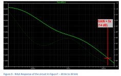
This looks like a pretty fine step-up replacement for the NE5534 in a standard MM RIAA amp - the noise from ~1k to about 40k looks to be that of a pure resistor. I'll have to get a few and play with them.
This looks like a pretty fine step-up replacement for the NE5534 in a standard MM RIAA amp - the noise from ~1k to about 40k looks to be that of a pure resistor. I'll have to get a few and play with them.
The CMOS parts are nice but 5V so not enough DNR for audio. A few folks here have used the de-comped AD745 for RIAA. If you find them unavailable I could send some from my private stash.
@Richard Sorry for OT, but this guy could use some advise about microphones for a cool project: EU round of subjective blind comparison of small fullrangers. Help needed.
Cheers!
Cheers!
The CMOS parts are nice but 5V so not enough DNR for audio. A few folks here have used the de-comped AD745 for RIAA. If you find them unavailable I could send some from my private stash.
Thanks Scott - I’ll try the 745 - I can probably get them from RS or Moser over here.
- Home
- Source & Line
- Analogue Source
- Richard Lee's Ultra low Noise MC Head Amp