Were the caps biased? (You write input shorted by the cap). I assume your measurement amp input is DC free. Without any voltage applied, the cap will have no leakage current and thus will not produce any noise.First is measuring preamp input shorted, second is with the input shorted by the cap. No noise difference that I can tell.
Were the caps biased? (You write input shorted by the cap). I assume your measurement amp input is DC free. Without any voltage applied, the cap will have no leakage current and thus will not produce any noise.
Biased at +2.4V (2 NiCd cells) through a large resistor. Measurement amp is of course AC, through a film cap.
That's a good article and it discusses important points in LN transformer design. In particularMethinks Scott was talking about the Lepaisant design. We discussed that years ago in sci.electronics.design.
< https://pdfs.semanticscholar.org/49b5/63335faea2836e65c6dee411d5c8b04d5a3e.pdf >
- FET i/p stage which will have Rni & Rnv very far apart compared with BJTs. GG Baxandall discusses this in his LN articles and IIRC had an expression for best NF achievable for a given Rni & Rnv. My single brain cell has long lost this except for the single datapoint of 3dB for common or garden CB which I thought was Duraglit's behaviour until put right by Gurus Wurcer & Hans 😱
- Transformer feedback which of course was used by GG Baxandall in times Jurassic even when I was a nipper. The advantage is it eliminates EVIL resistors in the feedback path from intruding into the sensitive 'input loop'. IIRC, da GG's circuit is simpler, more elegant and performs better than this. I suggested to Les Watts doing all the voltage gain in the transformer and using the OPA/FET just as a voltage follower cos you don't need resistors in a voltage follower. Royer may do something similar in their active ribbons
- However, for all the cleverness in the article, I don't think it even achieves 3dB NF. It's hard to make out but I think their Fig 5 shows they have 0R5 3dB NF at 77K and about 5dB at more comfortable temperatures 😱 Anyone have a clean original copy of the paper where this is clearer?
Thanks for this info, Gerhad.The Siemens N48 cores are as common as it gets. The ex Siemens ferrite division is now TDK-EPCOS.
I have never used these new fangled (not-so-Unobtainium) cores 😱 or even done a design exercise with them. I believe Marik uses something similar for his supadupa ribbon transformers and was (understandably) reluctant to divulge their nature and source.
Not so hard cos when you get to the impedance of a MC cartridge, you often find your LoZ winding is often only 1 turn. You need to use Cu tape or something similar to take full advantage of the bobbin space for LN/LF response/overload bla bla. If you were doing this commercially, you would talk to your supplier to see how he deals with 1T windings. Today, with SMPS everywhere, the expertise should be available.@Gerhard. How hard is winding one of those pot cores?
________________
Could you repeat these measurements with a amp which doesn't have an inherent rise in noise below 300Hz? It's likely the effects we are looking for are within this region. Perhaps a modified, high gain version of your lesser Leach that has been checked for noise rise. 🙂syn08 said:This is for the 493-3103-ND 3900uF/2.5V aluminum polymer, from 1Hz to 1KHz.
Last edited:
Thanks Gerhard. Something for me to park for the future. I had a 'meh' experience with a cheap transformer back in the 80s and never been tempted since, but this is interesting enough to put into the future projects pile for 2030* ish 🙂
*only partly a joke.
*only partly a joke.
Could you repeat these measurements with a amp which doesn't have an inherent rise in noise below 300Hz? It's likely the effects we are looking for are within this region. Perhaps a modified, high gain version of your lesser Leach that has been checked for noise rise. 🙂
That's not necessary. The capacitor's effect grows with 1/f**3 or 30 dB/decade.
It won't go unnoticed if it happens.
As Robert Gallo said about the HIV virus: You don't need co-factors if you are hit by a truck.
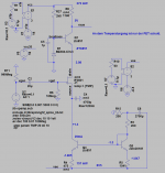
Maybe my circuit is extra sensitive against bad capacitors (C4 in the circuit); every electron that goes through the cap is missing from Is of the FET. The CCS was meant to fight gain error over temperature since gain is ~ sqrt(Is). It is still 0.8 dB/10°C (dependency on gate voltage), so the next version will warm the FET to 35°C.
Then the ado with the CCS may be superfluous. I did not want anything on the gate side except a >10 Meg pull down to GND and maybe a harder short for excessive input signals because I want to do cross correlation. Any input noise current from 1 of the 2 input amplifiers would create a common mode voltage drop across Zsource, and it would never average away from the cross spectrum.
Noise of the current mirror transistors matters, and also the decoupling of the reference midpoint.
I also have no idea yet why the noise of bad caps is 1/f**3, but the slope seems consistent across multiple "bad" types. Just different corner frequency.
Attachments
Last edited:
expression for best NF achievable for a given Rni & Rnv.
I said before noise figure is a useless concept for audio, power transfer is not important here. Paralleling JFET's is a constant win even keeping the total current constant (unlike bipolars) you gain the fourth root of two for each doubling forever until you get to subthreshhold. There is no best NF achievable theoretically.
Could you repeat these measurements with a amp which doesn't have an inherent rise in noise below 300Hz? It's likely the effects we are looking for are within this region. Perhaps a modified, high gain version of your lesser Leach that has been checked for noise rise. 🙂
Impossible; LF 1/f noise is ubiquitous, no way to avoid it. A LNA noise corner frequency of around 20-100Hz is the best you can do with electronics and without going into deep cooling. Perhaps transformers would help, but I have no desire to go there.
BTW, I’ve noted with those 3900u/2.5V aluminum polymer caps that noise increases quickly with frequency @100KHz and over, no idea why, also no idea if this behaviour is general or specific to this model.
If you don't mind Guru Wurcer, I'll keep using NF as the noise degradation of a resistive source.I said before noise figure is a useless concept for audio, power transfer is not important here.
This isn't the RF definition loved by da pedants but was used by the Broadcast Organisations, certainly the BBC, IBA, at least one Norwegian and one German Broadcast organisation in their Contract Specifications for microphone inputs on Broadcast Mixing Desks.
It's also very simple to understand and tells you exactly how much further improvement is possible.
Yes. Even a single FET or FET OPA gives excellent noise performance IF you can do a transformer winding in the 10s of K to match its Ropt = rt(Rni x Rnv) without the cons of HiZ transformer windings ... provided 1/f noise bla bla is within bounds.Paralleling JFET's is a constant win even keeping the total current constant (unlike bipolars) you gain the fourth root of two for each doubling forever until you get to subthreshhold. There is no best NF achievable theoretically.
But as with all things, there are limits if you want to build a practical device. With nearly all the amps here, you find your LN PSUs rapidly become more complex than the amp to retain the SOTA noise. The big advantage of battery Duraglit is mere mortals can achieve SOTA noise & other stuff very simply and without mucho $$$. The only slightly Unobtainium item is the Duraglit tin. 🙂
______________________
Mea culpa, mea culpa, mea maxima culpa.It's hard to make out but I think their Fig 5 shows they have 0R5 3dB NF at 77K and about 5dB at more comfortable temperatures 😱 Anyone have a clean original copy of the paper where this is clearer?
The 5dB difference at 200K is wrt to 0R5 @ 77K. So it is likely Lepaisant et al achieve 3dB NF at more comfortable temperatures ... which is still easily beaten by Duraglit and also several designers of mike preamps. The important factor in these transformer designs is still the transformer. 😀
Last edited:
I noise increases quickly with frequency @100KHz and over, no idea why, also no idea if this behaviour is general or specific to this model.
That is possibly induced current noise just as in the gate of a JFET.
The 5dB difference at 200K is wrt to 0R5 @ 77K. So it is likely Lepaisant et al achieve 3dB NF at more comfortable temperatures ...
Either you're just being difficult or you don't get it. The 0.06nV is all that matters I don't see any circuits here at that level (not that it matters). Two transistors with associated parts off a 1.5V battery won't do this at any current.
Last edited:
If you don't mind Guru Wurcer, I'll keep using NF as the noise degradation of a resistive source.
This isn't the RF definition loved by da pedants but was used by the Broadcast Organisations, certainly the BBC, IBA, at least one Norwegian and one German Broadcast organisation in their Contract Specifications for microphone inputs on Broadcast Mixing Desks.
It's also very simple to understand and tells you exactly how much further improvement is possible.
Not simple enough for me; could you please explain what exactly means, for example, in your acceptation, “1.7dB NF”.
Either you're just being difficult or you don't get it. The 0.06nV is all that matters I don't see any circuits here at that level (not that it matters). Two transistors with associated parts off a 1.5V battery won't do this at any current.
A 200R resistor or microphone has 1.8nV/rt(Hz) noise at 300K.Not simple enough for me; could you please explain what exactly means, for example, in your acceptation, “1.7dB NF”.
A BBC broadcast mixing desk contract would specify the equivalent input noise with a 200R resistor across pins 2 & 3 of the input microphone XLR should not exceed this by X dB. They would call this 'XdB NF'.
You could better my poor 1.7dB NF transformer efforts .. but not by more than 1.7dB
I quoted my example as a response to Guru Wurcer's question about transformers as to what is possible with a real life transformer design. Lepaisant et al only achieve 3dB NF so it is certainly possible to better that with a better transformer/amp combination.
But Eric & I weren't contemplating using 2 BJTs and a battery for our transformerless ribbon. To achieve 3dB NF with a 0R1 ribbon would need zillion ZTX851/951s and zillion mA in Duraglit. This would still be half the devices & mA required in lesser topologies.
A 200R resistor or microphone has 1.8nV/rt(Hz) noise at 300K.
A BBC broadcast mixing desk contract would specify the equivalent input noise with a 200R resistor across pins 2 & 3 of the input microphone XLR should not exceed this by X dB. They would call this 'XdB NF'.
You could better my poor 1.7dB NF transformer efforts .. but not by more than 1.7dB
I quoted my example as a response to Guru Wurcer's question about transformers as to what is possible with a real life transformer design. Lepaisant et al only achieve 3dB NF so it is certainly possible to better that with a better transformer/amp combination.
But Eric & I weren't contemplating using 2 BJTs and a battery for our transformerless ribbon. To achieve 3dB NF with a 0R1 ribbon would need zillion ZTX851/951s and zillion mA in Duraglit. This would still be half the devices & mA required in lesser topologies.
Ok, so some sort of relative equivalent noise resistance, expressed in dB. Trouble is, you almost never specify the reference resistive value. Please do so, even in the above example “1.7dB” is still ambiguous to me.
Noise figure as used in RF work has an unambiguous source resistance, so is useful when "noise matching" input transformer ratios and such. RF amplifier design can be optimized for a particular source resistance. Unless an audio amplifier has some impedance matching tradeoff involved it seems just an affectation.
An example of a helpful audio use of noise figure might be a moving magnet/iron/magic wand phono cartridge, with significant RLC source impedance. Here tradeoffs in input stage design are needed for specific RLC sources, optimums to converge on lowest noise figure.
This is not true for very low impedance sources, which can be designed without regard for source impedance. All designs are optimized for zero source resistance and source noise is simple and small.
All good fortune,
Chris
Chris: The problem with fixed coil cartridges is the impedance does change so IMO loading has to be primarily to get the frequency response correct. 47k is rarely the optimal loading! Luckily MM cartridges are not critical for noise except for bragging rights 🙂
I'm still confused over if the BBC noise figure is a power or voltage. For me noise figure is always a power.
I'm still confused over if the BBC noise figure is a power or voltage. For me noise figure is always a power.
In RF, impedance matching is mostly performed to avoid reflections and standing waves. When dealing with RF, wavelengths of signals is small compared to lengths of wires, PCB traces etc. Impedance mismatching leads to extremely uneven frequency response as depending on frequency a simple piece of wire (not connected to anything) can be an open for some frequencies while it can also be a short at others. To avoid such refelections, impedance matching is required. With matched impedances max. possible power is transferred.
All these aspects are completely irrelevant for audio as wavelengths in audio are huge compared to normal conductor lengths.
Nevertheless, dBs as units and NF etc can still be used and are absolutely ok; they are not reserved for RF only. But-when using such units it is absolutely mandatory to always give the reference (values referred to voltage, current, power, impedance etc) as all these units are not absolute but relativ. This is also true for RF but here at least some standards have been established but e.g. defining system impedance is still required (is it 50R, 75R or something else) - otherwise NF and dB values are meaningless.
Sigh ... its a Transformer example. I assume (like GG Baxandall) anyone designing a transformer i/p LN amp is versed in the art of designing/specifying/making an appropriate transformer to match any source .. whether 0R1, 10R or 200ROk, so some sort of relative equivalent noise resistance, expressed in dB. Trouble is, you almost never specify the reference resistive value. Please do so, even in the above example “1.7dB” is still ambiguous to me.
On the MC front, if I claim a certain Duraglit variant has 3dB NF with Ortofon MC20, I'm also claiming you can't better this performance by more than 3dB ... regardless of complexity, number of bits or zillion mA
On the transformer i/p LN design side, a closer look at Lepaisant et al shows they have 8 & 10T windings to match 0R5. This means their core isn't as good as the mu-metal ones I'm used to and favoured by Lundahl, Sowter & Jensen. This is certainly one reason why they only achieve 3dB NF
Don't get me wrong. I think its a good, if over complex, article .. but their implementation can be bettered by any number of old fogey Broadcast Mixing Desk Preamp designers .. (but only by slightly more than 1dB)
Marik uses 'ferrite' cores in his ribbon mikes so the ones he uses must outperform the usual mu-metal ones. I just wish I knew what he used. 🙁 But I'm certain it's not Siemens N48
Last edited:
I suggested we start a new thread on how to get supa LN for MM. This is far more difficult than what we are doing here for MCThe problem with fixed coil cartridges is the impedance does change so IMO loading has to be primarily to get the frequency response correct. 47k is rarely the optimal loading! 🙂
It's a measurement. YouI'm still confused over if the BBC noise figure is a power or voltage. For me noise figure is always a power.
- measure output noise with your resistor stuck across XLR i/p pins 2 & 3
- divide by the gain
- compare with the Johnson noise of the resistor you used
Last edited:
I think you are missing the fact that the transformer AND the amplifier input Z matter?Sigh ... its a Transformer example. I assume (like GG Baxandall) anyone designing a transformer i/p LN amp is versed in the art of designing/specifying/making an appropriate transformer to match any source .. whether 0R1, 10R or 200R
I think you are mixing up relative vs absolute noise here?Don't get me wrong. I think its a good, if over complex, article .. but their implementation can be bettered by any number of old fogey Broadcast Mixing Desk Preamp designers .. (but only by slightly more than 1dB)
Been done. Winner is Grado if low noise is your goal.I suggested we start a new thread on how to get supa LN for MM. This is far more difficult than what we are doing here for MC
It's a measurement. You
- measure output noise with your resistor stuck across your XLR i/p pins 2 & 3
- divide by the gain
- compare with the Johnson noise of the resistor you used
The way you have described I still don't know if its power or voltage.
- Home
- Source & Line
- Analogue Source
- Richard Lee's Ultra low Noise MC Head Amp