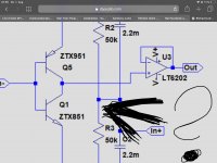
Here is the new design for the Phantom powered Head Amp's sub-circuit.
Same as before two versions, a voltage input and a current input.
What is shown is meant for a 0.1mV 1 Ohm cart, needing a Gain of 50.
In this example, simulated noise is 350pV/rtHz.
Because it is a diff-in circuit (yes I know, not everybodies first choice), there is a 3dB noise penalty.
In a SE version this translates to 250pV/rtHz, which is the same as the simulated Duraglit at 2.75mA collector current.
This 2.75mA is the maximum current for a diff version fed by Phantom power.
Input impedance is 125 Ohm per amp (R12//R13), two in series resulting in 250 Ohm.
For a Cart with a higher output voltage, these 250 Ohm resistors can easily be enlarged in value if needed, thereby reducing the collector currents.
Building these amps as intended will enable to do measurements for verification of the Sims, without any further intention ever to sell.
But after having tested, everybody can have the Gerbers for free.
Hans
P.S. R1 and R3 in the current input version should be 25 Ohm instead of 24.5 Ohm.
If I'm not mistaken, a statistically 1mV average offset voltage (really, defined by the delta Vbe's) will create a probable 1/SQRT(2)/(1+Rs) [mA] cartridge current. Isn't that a little too much?
Last edited:
Thank you for making me aware.If I'm not mistaken, a statistically 1mV average offset voltage (really, defined by the delta Vbe's) will create a probable 1/SQRT(2)/(1+Rs) [mA] cartridge current. Isn't that a little too much?
The Non Inverting version is almost insensitive to such Vbe offset voltages, and only needs accurate 50k resistors.
The Inverting version is indeed very sensitive to Vbe differences.
When giving a 1mV offset in the shown circuit diagram, the Sim shows an absolutely intolerable 0.5mA Cart current (1/(1+Rs))
I'll have to repair this, preferably without the LT1884 servo that I used before that cured this offset problem.
Hans
Hi Hans.
I have seen simelar circuit like your Curl7.asc.
with only 1Vpp headroom between XTX851 and 951, the smallest offset on the collector point will give rise to 2.order harmonics very fast. order 0.1% to 0.5% with a few hundred mV.
But when i look closer on your design i can see that you use negative feedback... So it will stay in the middle.
The design i refer to did not use feedback and had a resistor to ground. .... Very badly designed. With bias current ic of 20mA
What is acceptable values of MC coil current? 10 - 20uA?
What is acceptable values of MC coil current? 10 - 20uA?
A good question for which there is no simple answer. In the case of Hans his cartridge replacement cost is somewhat higher than any of mine, so he will go by the manufacturer recommendations. In tests several mA does not have any measurable effect on the cartridge and certainly will not melt the wiring.
BUT...other than me not sure many are willing to take the risk.
AND.. It IS good practice to minimise things like this anyway.
That is the big question, but it surely depends on the Cart used.Hi Hans.
What is acceptable values of MC coil current? 10 - 20uA?
A 0.1mV 1 Ohm cart, sources 100uA at 5cm/sec@1Khz.
A 0.5mv 50 Ohm cart only 10uA under the same circumstances.
But I agree that 10-20uA DC current as a general target seems quite O.K.
Hans
That is the big question, but it surely depends on the Cart used.
A 0.1mV 1 Ohm cart, sources 100uA at 5cm/sec@1Khz.
A 0.5mv 50 Ohm cart only 10uA under the same circumstances.
But I agree that 10-20uA DC current as a general target seems quite O.K.
Hans
Hans i would if i may suggest anything... But a series damping resistor on the capacitor C1 and C2 of 10ohm. It does not matter a lot for the total gain. Noise will go up a little but it could prevent oscillation.
Thank you for making me aware.
The Non Inverting version is almost insensitive to such Vbe offset voltages, and only needs accurate 50k resistors.
The Inverting version is indeed very sensitive to Vbe differences.
That’s to be expected if one recognizes your “low noise op amp” as being in fact (Bonsai will be delighted) a current feedback op amp, with its known issues in inverting configuration.
Last edited:
I might tend to worry more about turn-on and turn-off currents through the cartridge, if at all.
All good fortune,
Chris
All good fortune,
Chris
That’s to be expected if one recognizes your “low noise op amp” as being in fact (Bonsai will be delighted) a current feedback op amp, with its known issues in inverting configuration.
I am de-lited
That’s to be expected if one recognizes your “low noise op amp” as being in fact (Bonsai will be delighted) a current feedback op amp, with its known issues in inverting configuration.
What’s in a name.
I may hope it doesn’t trigger the whole CFA discussion again. 😀
Hans
P.S. Our famous football player Johan Cruijff once said “every disadvantage has it’s advantage”.
I agree with that.
Last edited:
Thanks for the suggestionHans i would if i may suggest anything... But a series damping resistor on the capacitor C1 and C2 of 10ohm. It does not matter a lot for the total gain. Noise will go up a little but it could prevent oscillation.
Hans
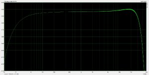
Not sure what you mean by "bandwidth" in this context? 20KHz loopback quick snapshot is attached, exactly what I would expect, minus the annoying 8KHz harmonic pips. For for $250 canadian tax included you cannot beat this (www.amazon.ca has them in stock, BTW, with free 1 day delivery for Prime members)
Thanks for that. I did really want the frequency response, I have enclosed the results for my Scarlett 2i4 Mk 1 for clarity - apologies if I was not clear enough in my request!

I'm hoping that with the higher sampling rate of the Mk 3 versions of the Scarlett's (192Khz), the upper frequency response will be higher. And the noise floor results you recorded look impressive, am I correct to assume from your enthusiasm that such is about as good as it gets from a USB Sound Interface?
Thanks for this aboos. This is indeed a good summary. For me, it has resurrected some really poignant memories, explained stuff which has bothered me for nearly 40 yrs. and improved the design furtherHere an attempt of a short summary of what have been the most useful findings so far:
- this thread started out with a collection of MC Headamp circuits put into one document by Bonsai. This docu got more and more comprehensive with a lot of additions from various contributors. Thank you Bonsai for doing so; your compendium is a very valuable collection of information now
- LTSpice is able to accurately sim (at least thermal resistor / Johnson noise) if transistor models are correct especially for the Rbb parameter. Unfortunately most models are absolutely incorrect and manufacturers do not provide accurate data anymore as nobody seems to be interestted in audio applications any more
- the ZTX 851/951 pair seems to be the only (known so far) BJT pair with excellent low noise performance currently still in production. Unfortunately this performance was an unintended side effect when they got designed and is neither specified nor tested. But we now have some characterization available and for very critical noise performance, selection may be required.
- electrolytic capacitors (of any variety) in critical places (mostly coupling/decoupling in input stage) still may require selection as some are good noisewise and others not so good
- a lot of basic dependencies between operating point, component selection, circuit topologies, generator source resistanve ... have been analyzed and put into nice graphs and charts
- floating versus grounded power supply pros and cons have been discussed and it was demonstrated that for a floating supply not only simple batteries are feasable but also solar cells. Maybe some more investigations need to take place to find out what OP and what type of cells are best noisewise and why.
- PSRR was investigated at least on basis of simulation. PSRR for floating supply circuits can be quite good contrary what one would initially assume
- circuits with rock solid DC stability vs. (a little bit) simpler circuits were discussed showing their pros and cons. A lot of choices are available to select from depending on your design goals, requirements and personal preferences
- it has been reported by some posters that running MC cartridges in 'current mode' does not lead to bad sound and that it is a very valid mode of operation
- and lastly, there could also be some solutions feasable for 'exotic' MC cartridges with exceptional low internal resistance and/or low output voltage
- why I could only equal but not beat Duraglit's performance with efforts rivalling syn08 & Gerhad in complexity & cost in 1980
- Duraglit was even better than I thought and never relinquished the title of lowest noise MC head amp until last month.
- Its noise performance is actually CE rather than CB
- improved LF design principles compared to my 1980 pseudo efforts
- solar cell powering opening the way to zillion mA and even lower noise
Those versed in the art will have realised that in spite of my sniping, syn08's #375 lesser Leach, if properly housed, will probably take over the title of lowest noise real life MC amp because of its zillion mA current. 😱 Of course, it can't claim the title until it is actually used for the purpose to confirm this.
A true Duraglit running the same current and using the same devices & capacitors will easy beat it but has yet to be built in .. I'm hoping Bill will do the honours 🙂
______________________________
BTW, the Duraglit tin is only slightly tongue-in-cheek. It has practically ideal characteristics for a very low noise MC amp because of its overlapping joints.
To minimise the holes in the lid which let in evil hum etc, today I would use a single Neutrik mini 5p XLR combining in/out (more pins for 2 wire in and/or power) ... or more simply, attached cables. I think the tin could easily contain syn08's PCB
A true hand-carved-from-solid-Unobtainium-by-Virgins construction would be to use the exact Duraglit shape & construction but from a soft iron / mu-metal laminate.
___________________
Could someone (Hans or aboos?) please do a PSRR sim of syn08's #375 circuit and compare it to Duraglit? Same current, devices & capacitors please. I suspect this might explain some of his findings.
Last edited:
Guru Hans, I wish you hadn't posted your Curl7.ascIn a SE version this translates to 250pV/rtHz, which is the same as the simulated Duraglit at 2.75mA collector current.
This 2.75mA is the maximum current for a diff version fed by Phantom power.
You keep tempting me to abandon beach bum stuff to try & get LTspice stuff up & running again at Cooktown Recording & Ambisonic Productions 🙂
This MC stuff is really willy-waving for me as I've got rid of my record collection. But Eric Benjamin & I were toying with a transformerless ribbon mike using Duraglit. Though it has better noise using less current than any competing topology, I was still nervous about running so much current near a precious ribbon (As a real mike & speaker guru and only a pseudo cartridge ex-guru, I value mikes & speakers more than cartridges)
Your #655 insight allows Duraglit performance somewhat more safely so we might re-surrect this. BTW, the H&H ribbon amp represents a serious danger to ribbons.
Even a very large & $$$ transformer would, at best, achieve 1.5dB NF so this is a 21st century real life application which would truly benefit from Duraglit performance and not attract Guru Wurcer's wrath 😀
Could someone (Hans or aboos?) please do a PSRR sim of syn08's #375 circuit and compare it to Duraglit? Same current, devices & capacitors please. I suspect this might explain some of his findings.
I just simmed both circuits set for identical Ic currents and gains (however base capacitors are different as Syn08's circuit requires high values to achieve a flat frequency response down to 20 Hz or lower, values do not influence the PSRR!). Source resistance was set to 10R.
- PSRR for both is at levels in the 60 dB range from 10Hz up to a few kHz
- Syn08's variant is a little bit better (approx 4 to 5dB)
- from 8kHz on, PSRR for both circuits is reduced by 10 to 12 dB to 45 to 47 dB at 100 kHz
- below 10 Hz, Duraglit shows a slight bump down to 42 dB at 1 Hz (this bump depends on the base capacitors, larger values will eliminate this bump)
- to even lower frequencies, PSRR gets better for both up to 70 dB at .1 Hz
Why are the PSRR values so good for both and why is Syn08's a little bit better?
PSRR is high due to the floating power supply. Any noise on the power supply is symetrical and equal for both the + as for the - rail. Due to the complementary designs, such noise is canceled at the output (a sort of common mode rejection). The level of suppression depends on the symmetry of the transistors and with the ZTX LTSpice models around 60 dB are achieved. The PSRR reduction starting at a couple of kHz is due to the differences in the differing capacitances (Ccb, Cce) of the complementary transistors. Also the 60dB value is due to the fact that npn and pnp are never exactly symetric, if they would be exactly symetric, PSRR would be extremely high. Be aware that all other parts (resistors and capacitors) are absolutely identical in LTSpice.
Syn08's circuit is a little bit better as the current mirrors and the very slight degeneration introduced by the small emitter resistors make the circuit a little bit more symetric by reducing the effects of differences in the transistors.
Last edited:
I just simmed both circuits set for identical Ic currents and gains (however base capacitors are different as Syn08's circuit requires high values to achieve a flat frequency response down to 20 Hz or lower, values do not influence the PSRR!). Source resistance was set to 10R.
- PSRR for both is at levels in the 60 dB range from 10Hz up to a few kHz
- Syn08's variant is a little bit better (approx 4 to 5dB)
- from 8kHz on, PSRR for both circuits is reduced by 10 to 12 dB to 45 to 47 dB at 100 kHz
- below 10 Hz, Duraglit shows a slight bump down to 42 dB at 1 Hz (this bump depends on the base capacitors, larger values will eliminate this bump)
- to even lower frequencies, PSRR gets better for both up to 70 dB at .1 Hz
Why are the PSRR values so good for both and why is Syn08's a little bit better?
PSRR is high due to the floating power supply. Any noise on the power supply is symetrical and equal for both the + as for the - rail. Due to the complementary designs, such noise is canceled at the output (a sort of common mode rejection). The level of suppression depends on the symmetry of the transistors and with the ZTX LTSpice models around 60 dB are achieved. The PSRR reduction starting at a couple of kHz is due to the differences in the differing capacitances (Ccb, Cce) of the complementary transistors. Also the 60dB value is due to the fact that npn and pnp are never exactly symetric, if they would be exactly symetric, PSRR would be extremely high. Be aware that all other parts (resistors and capacitors) are absolutely identical in LTSpice.
Syn08's circuit is a little bit better as the current mirrors and the very slight degeneration introduced by the small emitter resistors make the circuit a little bit more symetric by reducing the effects of differences in the transistors.
For those reading, this is the right way to use a simulator (if one wants to do more than cobble a circuit for quick results). Simulate, observe the results, phenomenologically understand the results (something the simulator is never going to tell you), draw conclusions about how to improve the behavior, iterate if needed. Congratulation!
Thanks for that. I did really want the frequency response, I have enclosed the results for my Scarlett 2i4 Mk 1 for clarity - apologies if I was not clear enough in my request!
I'm hoping that with the higher sampling rate of the Mk 3 versions of the Scarlett's (192Khz), the upper frequency response will be higher. And the noise floor results you recorded look impressive, am I correct to assume from your enthusiasm that such is about as good as it gets from a USB Sound Interface?
Attached. High frequency response is IMO superb, LF could be better, but it's only a matter of replacing a few caps (if one really thinks it's worth of).
Yes, this is as good as an USB sound card could be, I've never seen anything better (although it could exist, I don't claim I've seen them all). All for 150 of your pounds.
Attachments
- Home
- Source & Line
- Analogue Source
- Richard Lee's Ultra low Noise MC Head Amp