I do not completely agree with your sense of humour.
I wouldn't have expected it. I just found the idea of half a dozen words on an obscure forum warranting a phone call to be amusing. The other interpretations did not bear consideration...
Purely personally I think this thread stands out like a refreshing craft beer in a sea of Coors light (other cr*p tinned plastic beers are available). Give or take the odd pages of wibble that always happen a number of solutions are presented, analysed and a few built. Someone finding this thread in the future can read through and have informed information to make a decision on if they want to go hair shirt or civilised.
Here an attempt of a short summary of what have been the most useful findings so far:
- this thread started out with a collection of MC Headamp circuits put into one document by Bonsai. This docu got more and more comprehensive with a lot of additions from various contributors. Thank you Bonsai for doing so; your compendium is a very valuable collection of information now
- LTSpice is able to accurately sim (at least thermal resistor / Johnson noise) if transistor models are correct especially for the Rbb parameter. Unfortunately most models are absolutely incorrect and manufacturers do not provide accurate data anymore as nobody seems to be interestted in audio applications any more
- the ZTX 851/951 pair seems to be the only (known so far) BJT pair with excellent low noise performance currently still in production. Unfortunately this performance was an unintended side effect when they got designed and is neither specified nor tested. But we now have some characterization available and for very critical noise performance, selection may be required.
- electrolytic capacitors (of any variety) in critical places (mostly coupling/decoupling in input stage) still may require selection as some are good noisewise and others not so good
- a lot of basic dependencies between operating point, component selection, circuit topologies, generator source resistanve ... have been analyzed and put into nice graphs and charts
- floating versus grounded power supply pros and cons have been discussed and it was demonstrated that for a floating supply not only simple batteries are feasable but also solar cells. Maybe some more investigations need to take place to find out what OP and what type of cells are best noisewise and why.
- PSRR was investigated at least on basis of simulation. PSRR for floating supply circuits can be quite good contrary what one would initially assume
- circuits with rock solid DC stability vs. (a little bit) simpler circuits were discussed showing their pros and cons. A lot of choices are available to select from depending on your design goals, requirements and personal preferences
- it has been reported by some posters that running MC cartridges in 'current mode' does not lead to bad sound and that it is a very valid mode of operation
- and lastly, there could also be some solutions feasable for 'exotic' MC cartridges with exceptional low internal resistance and/or low output voltage
yeah reckon that covers it (as an owner of one of the exotics). But one thing I would add as an interesting learning is the part that, for the duraglit variants gain does not depend on Hfe. One of the negatives people have thrown up over the ZTX parts is the low Hfe compared with unobtanium parts.
The ZTX also work rather well in a demrow style circuit and the bonkers H&H ribbon preamp.
The only bit missing is if there is a way to get it to work well in a phantom powered application.
The ZTX also work rather well in a demrow style circuit and the bonkers H&H ribbon preamp.
The only bit missing is if there is a way to get it to work well in a phantom powered application.
Nice summary Andreas.
"- and lastly, there could also be some solutions feasable for 'exotic' MC cartridges with exceptional low internal resistance and/or low output voltage "
Please see the 'Weinberg'. Its nasty because you have to match 6 Vbe's but if you are using an exotic cartridge, you will in any event have to go to extraordinary lengths - the other would be a good quality SUT which would not be cheap.
The simulated total noise is c. 250 pV/rt Hz with a 3 Ohm Rgenerator and it is simply a development of Richards Duraglit.
@billshurv, the Demrow is very good, but it's not as good as the Duraglit's (and the paralleled versions of those) in terms of absolute noise IMV.
Re syn08's Jean Hiraga look alike, am I correct in that the emitters of the two bias transistors are not connected to ground?
@billshurv, the Demrow is very good, but it's not as good as the Duraglit's (and the paralleled versions of those) in terms of absolute noise IMV.
It's not but for all the sane MCs in my collection is it more than adequate when you want 60ish dB of gain to feed straight into an ADC as a flat balanced preamp. It just ticks all the boxes for my current analog perversions for my main amp. The common base derivatives are reserved for my silly carts.
May I ask what your really silly carts are?
The most extreme I ever saw is a cart with only one single wire (even not a 'coil') in the magnetic field gap. Can't remember what exactly brand and type it was.
The most extreme I ever saw is a cart with only one single wire (even not a 'coil') in the magnetic field gap. Can't remember what exactly brand and type it was.
Bill,yeah reckon that covers it (as an owner of one of the exotics). But one thing I would add as an interesting learning is the part that, for the duraglit variants gain does not depend on Hfe. One of the negatives people have thrown up over the ZTX parts is the low Hfe compared with unobtanium parts.
The ZTX also work rather well in a demrow style circuit and the bonkers H&H ribbon preamp.
The only bit missing is if there is a way to get it to work well in a phantom powered application.
Do you remember this posting for a phantom version based on the same ZTX transistors ?
Designing a universal diff-in/diff-out Head Amp
Because of all the discussions in this thread, I did a re-design where I could eliminate the LT1884 and the PS transistor, simply by replacing them all by 2 resistors !!
Because I still like the idea to have the alternative of voltage or current steering, I compared the JC circuit with the Duraglit by Simming them.
Since noise and THD performance are almost equal, I still prefer the JC topology especially with the addition of the LT6202, because
1) Gain in the non inverting mode is independent of Rcart and easy to calculate (1+(R1+R3)/R12).
2) High input impedance in the non inverting mode, enabling the use of a proper termination resistor
3) Can also be used in inverting mode where Gain is just simply Rf/Rcart
4) Has low output impedance because of LT6202
So I will publish the redesigned version shortly, plus a PCB design enabling with jumpers the selection for voltage or current input.
The ZTX part will be placed on a separate piggyback PCB, enabling this part to be replaced by another design such as a AD797 or a Duraglit.
That's why, to make Richard happy, I will also show a circuit diagram for a Phantom version with the Duraglit.
Hans
@Aboos: I think you are referring to the Nagatron ribbon cartridge. That is truly daft and I want one.
At the moment I have nothing seriously below 0.2mV (although there are at least 3 specs for my ASAK so I need to actually measure that) but I do have a desire for one of the early MC30s which are sub 1mV. I did wean myself off wanting an MC2000 after about 30 years 🙂. So realistically I could limp by with a 0.4nV/rtHz MC stage and not suffer, but I would like to be prepared should I do somthing loopy like getting a 1 ohm coil wound for an experiment.
@Hans: yes I remember that, have it printed out on my desk! I had parked that as concerned that consumer and prosumer mic interfaces may not actually meet the phantom power spec fully and have enough current to drive that.
@Aboos: I think you are referring to the Nagatron ribbon cartridge. That is truly daft and I want one.
Crazy stuff the daft people you find searching for this stuff is even crazier. That cart had an active pre-amp apparently with the usual hand picked paralleled unobtainium JFET's, powered by 8 D cells.
When I remember correctly, I had used the supply specs from your DSP unit, so it should not be a problem.@Hans: yes I remember that, have it printed out on my desk! I had parked that as concerned that consumer and prosumer mic interfaces may not actually meet the phantom power spec fully and have enough current to drive that.
Apart from that, making the the LT1884 obsolete and dropping the supply voltage means less power supply needed which may optionally be used to increase the current in the ZTX pair to even lower their noise contribution.
Hans
The focusrite should behave. My M-audio doesn't. But I will put it back on the list of things to build one day 🙂
Crazy stuff the daft people you find searching for this stuff is even crazier. That cart had an active pre-amp apparently with the usual hand picked paralleled unobtainium JFET's, powered by 8 D cells.
Yes even without the preamp they are very collectable. I do wonder what drives up the prices of some old stuff. I guess every country has its equivalent of Romy bigging up certain parts.
syn08's Jean Hiraga look alike, am I correct in that the emitters of the two bias transistors are not connected to ground?
No ground there; a ground connection there would defeat the whole purpose of the arrangement. Since the power supply is floating, the only condition that is enforced is the sum of transistors currents to be zero. As such, with a ground connection, the currents through all 4 transistors would be ill defined (instead of having them well defined by R100/R106 only). The DC balance would then be lost. Exact schematic is in #375.
No ground there; a ground connection there would defeat the whole purpose of the arrangement. Since the power supply is floating, the only condition that is enforced is the sum of transistors currents to be zero. As such, with a ground connection, the currents through all 4 transistors would be ill defined (instead of having them well defined by R100/R106 only). The DC balance would then be lost. Exact schematic is in #375.
got it - thanks
The focusrite should behave. My M-audio doesn't. But I will put it back on the list of things to build one day 🙂
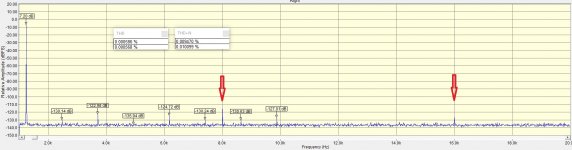
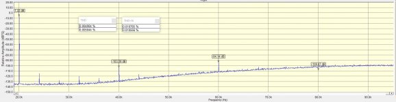
Because you mentioned it, I just received yesterday a brand new FocusRite 2i2 3rd generation (couldn't resist having one of these 🙂. It is indeed outstanding what the FocusRite engineers were able to pull out of a rather mediocre D/A + A/D chip (CS4272, same along all FocusRite USB interfaces generations). -140dB noise floor (192KHz, 1M samples, Hanning window), 0.0004% THD @1KHz and 0.0020% THD @20KHz. I'll open the case and get rid of those NJM op amps ASAP and see where this goes (in particular @20KHz). The performance is about twice as good compared with the 2nd generation 2i2. The only annoying issues is the same as in previous generations, an ugly 8KHz (and harmonics) residual that forces you to set the output frequency at 1131Hz instead of 1000Hz, otherwise the THD measurements are affected. THD+N measurements are affected by the same residual.
Ah, and the (only) 2ft. USB cable. Why are people so cheap? Reminds me of my kitchen mixer that came with a 40cm long power cord. A quick snapshot is attached.
Attachments
Last edited:
Because you mentioned it, I just received yesterday a brand new FocusRite 2i2 3rd generation (couldn't resist having one of these 🙂. It is indeed outstanding what the FocusRite engineers were able to pull out of a rather mediocre D/A + A/D chip (CS4272, same along all FocusRite USB interfaces generations). -140dB noise floor (1M samples), 0.0004% THD @1KHz and 0.0020% THD @20KHz. I'll open the case and get rid of those NJM op amps ASAP as soon as I have a chance and see where this goes (in particular @20KHz). The performance is about twice as good compared with the 2nd generation 2i2.
I have asked Focusrite for the bandwidth of this interface (hopefully above the quoted 20KHz), have you tested it yet to determine such as I would interested in the results? Focusrite mentioned such info may be restricted...sigh!
I will slum it with a 2nd gen 6i6 for the time being. It's good enough for vinyl experiments and I have a TI PCM4222 EVM coming my way at some point. For VFM its hard to beat!
I have asked Focusrite for the bandwidth of this interface (hopefully above the quoted 20KHz), have you tested it yet to determine such as I would interested in the results? Focusrite mentioned such info may be restricted...sigh!
Not sure what you mean by "bandwidth" in this context? 20KHz loopback quick snapshot is attached, exactly what I would expect, minus the annoying 8KHz harmonic pips. For for $250 canadian tax included you cannot beat this (www.amazon.ca has them in stock, BTW, with free 1 day delivery for Prime members)
Attachments
Last edited:
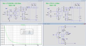
Here is the new design for the Phantom powered Head Amp's sub-circuit.
Same as before two versions, a voltage input and a current input.
What is shown is meant for a 0.1mV 1 Ohm cart, needing a Gain of 50.
In this example, simulated noise is 350pV/rtHz.
Because it is a diff-in circuit (yes I know, not everybodies first choice), there is a 3dB noise penalty.
In a SE version this translates to 250pV/rtHz, which is the same as the simulated Duraglit at 2.75mA collector current.
This 2.75mA is the maximum current for a diff version fed by Phantom power.
Input impedance is 125 Ohm per amp (R12//R13), two in series resulting in 250 Ohm.
For a Cart with a higher output voltage, these 250 Ohm resistors can easily be enlarged in value if needed, thereby reducing the collector currents.
Building these amps as intended will enable to do measurements for verification of the Sims, without any further intention ever to sell.
But after having tested, everybody can have the Gerbers for free.
Hans
P.S. R1 and R3 in the current input version should be 25 Ohm instead of 24.5 Ohm.
Attachments
Last edited:
- Home
- Source & Line
- Analogue Source
- Richard Lee's Ultra low Noise MC Head Amp