XRK,
thanks for the comprehensive reply.
And a pity because the 2 transformers in my possession would be potentially suitable, 500VA from which to be able to extract the 2x0-36V, so I would not have had power problems. But the most important observation "But the DC set-points may be far enough away from nominal that a whole rejiggering of resistors might need to ensure proper operation and stability" forces me to make a really careful evaluation in undertaking this really interesting project . Congratulations for it. Thanks for the help e
good continuation. Greetings to all.
Mleod
Off my original design, I can't see anything serious about reducing voltage from 36Vac to 30Vacor anything in between which would affect operation....... It would work just fine. There would be higher dissipation, much more heat on each device, but nothing big mosfets cannot handle. And the earlier stages would cope without problem either.
HD
HD
Last edited:
Hiyas, another potentially silly question:
C104, C113 schematic says 1000uf, BOM and original AKSA schematic says 100uf. Which should I go with? 🙂 Thanks.
C104, C113 schematic says 1000uf, BOM and original AKSA schematic says 100uf. Which should I go with? 🙂 Thanks.
Modeling the output of push-pull stages of classes A and AB without taking into account the coverage of their total negative feedback is very clear. This shows a very wide range of frequency distortions including 11 and even 17 and more harmonics even at their acceptable level. All the schemes used now are outdated 40-50 years ago.
Try 470uF, nice compromise, removes the nasty thump at switch on.
HD
Thanks mate, will do 🙂
Gunfu,
This is a single ended Class A amp with an reactive CCS (the Aleph part of it), not a push-pull amp.
Please enlighten us with what is missing in the model below:
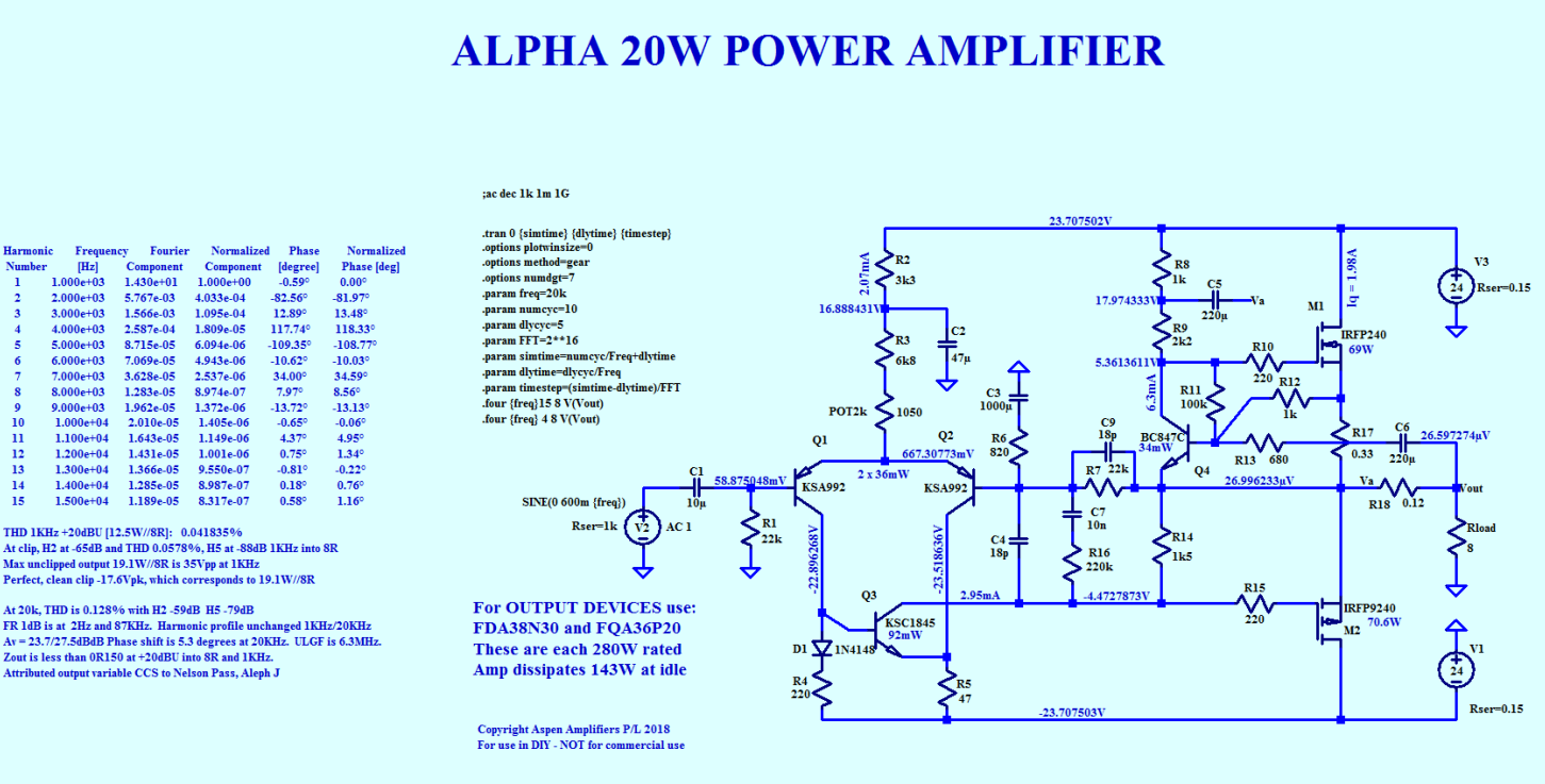
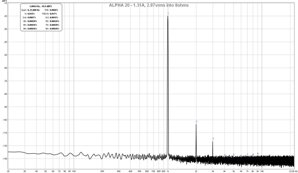
And BTW, the measurements match the model very well - only 2nd harmonic and a little 3rd, no nasty higher 11 and 17 harmonics of any significance.
Modeling the output of push-pull stages of classes A and AB without taking into account the coverage of their total negative feedback..
This is a single ended Class A amp with an reactive CCS (the Aleph part of it), not a push-pull amp.
Please enlighten us with what is missing in the model below:
And BTW, the measurements match the model very well - only 2nd harmonic and a little 3rd, no nasty higher 11 and 17 harmonics of any significance.
Last edited:
I will clarify. I wrote about powerful push-pull symmetrical output stages that are not covered by a common negative connection on additional transistors of class A or AB, which have at least 50 V on one shoulder and the same on the other.
In your version, this SE is covered with feedback, and its power is low.
If you want to have an exact comparison, then it is very important that any one parameter of the compared amplifiers match. For example, they must have the same power. Power 200-300 W is now the usual power for modern speakers with a sensitivity of 90 dB / 1 meter - 1 W, to create a sound pressure, for example, like a 110dB piano.
It is even simpler and more objective to compare only the output stage, without embracing it by a common negative connection.
For example, my research showed that the optimal quiescent current for bipolar transistors that are currently popular is a current in the range of 70-80 mA. In the book of Bob Cordell, these data coincided.
Accordingly, even this very simple study shows that it opens up new great opportunities in creating powerful output stages with high efficiency, with a very low level of distortion and a short spectrum. But for some reason no one else uses it.
Last edited:
Hmm...
It was mentioned "Then use your favorite 1uF to 10uF (depending on how deep you want your bass to go before rolling off) MKP 400V axial boutique cap on the input. "
Just to confirm - bigger cap = moar bass? So 10 uF is optimal?
It was mentioned "Then use your favorite 1uF to 10uF (depending on how deep you want your bass to go before rolling off) MKP 400V axial boutique cap on the input. "
Just to confirm - bigger cap = moar bass? So 10 uF is optimal?
Not really, unless you call the output below 5Hz also bass.Just to confirm - bigger cap = moar bass? So 10 uF is optimal?
The input stage has an RC high-pass filter,
with 10uF and 22k the pole is at 0.7Hz,
with 4.7uf and 22k it's 1.5Hz,
2.2uf and 22k is 3.3Hz
RC High-pass Filter Design Tool
You won't hear the difference.
You won't hear the difference.
If using boutique caps, you will hear the difference in the cha-ching sound of the cash register. 🙂
Not really, unless you call the output below 5Hz also bass.
The input stage has an RC high-pass filter,
with 10uF and 22k the pole is at 0.7Hz,
with 4.7uf and 22k it's 1.5Hz,
2.2uf and 22k is 3.3Hz
RC High-pass Filter Design Tool
You won't hear the difference.
Hi Danny - did you mean 220k ohm resistor? I don't see 22k in the schematic...
The 22k is between the base of the input transistor and ground. This resistor sets the bias voltage at the input transistor and the value largely sets the input impedance to the first stage. That impedance with the input cap sets the corner frequency - the 1dB down point.
HD
HD
The 22k is between the base of the input transistor and ground. This resistor sets the bias voltage at the input transistor and the value largely sets the input impedance to the first stage. That impedance with the input cap sets the corner frequency - the 1dB down point.
HD
Hi Aksa - the Alpha BB has a 220k resistor shown on the schematic. Is this correct?

Yes correct, but it's on the signal size of the cap and used only to remove thumps when you attach a RCA source when the amp is on. It is far higher than the 22k (18k indicated on this schematic, slight change) and does not much change the corner frequency which is dominated by the base to ground resistor which is 10 times lower.
HD
HD
Yes correct, but it's on the signal size of the cap and used only to remove thumps when you attach a RCA source when the amp is on. It is far higher than the 22k (18k indicated on this schematic, slight change) and does not much change the corner frequency which is dominated by the base to ground resistor which is 10 times lower.
HD
Thanks AKSA just making sure schematic values all good before I press go in Mouser 🙂
Yes, sorry about that. Will edit now.
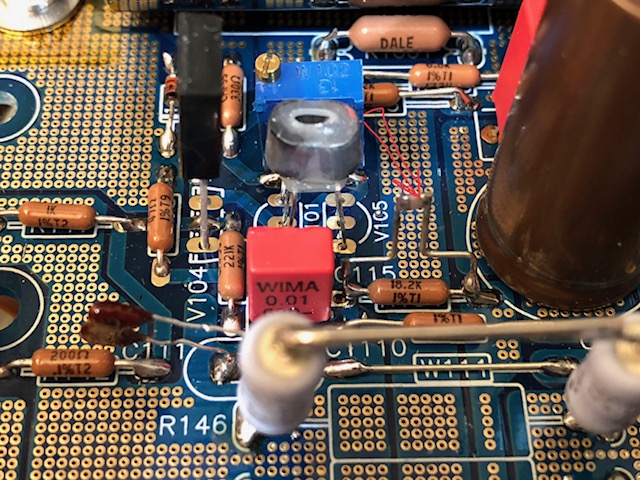
Here is the little through hole 22pF cap I made by soldering two legs into an 0805 SMT 22pF NP0. Then I straddled it across R154.
Hi X - hope you're not getting sick of my questions ><
In regards to the mod with 22 pf in parallel with R154 - when disconnecting C111, are you using a wire to bridge across it's pads (refer sketch)? Otherwise how is V111 emitter connected to base of V105?
Thanks as usual 🙂

- Home
- Amplifiers
- Solid State
- Aksa Lender P-MOS Hybrid Aleph (ALPHA) Amplifier