You are talking here of the ALPHA20 4R version, or the BB? I will respond with the 20/4R version, the smaller amp.
Sorry if I was unclear, and thank you for verifying. Yes, I'm speaking strictly of the Alpha20 4R, as I don't really need the extra oomph of the BB, and really would like to avoid active cooling.
double check the impedance curve of your loudspeaker as there are several versions of the Alpha 20 you can build from a low bias of 1.35A to higher biases of 2.4A...
Using the schematic on post 2780, as well as the changes mentioned on post 2789 and reading through Danny_66's post 3201, I determined that for my purposes, I can build an amp that has about 94+ watts of heat dissipation/ch (+/- 24V @ 1.96A) and can be passively cooled using a 5U/400 chassis. I will be using an SLB supply as you are planning. For a soft start I have Neurochrome's excellent ISS board I have already built.
The 5U is OK for two channels, but count on sinking 120W of heat on each heatsink for each channel. This is 2 x 24V x 2.5A = 120W plus 1st/2nd stages, and this stresses even large heatsinks.
Thanks so much for your replies Anand and Hugh. I think you might be right on the heat and compromise. I checked the speakers I'm planning to build and my current ones and they both seem relatively well-behaved 8-ohm speakers. I just worry I might come across some life changing 4-ohm design... However, I doubt it as high-efficiency and 8-ohms seems to be a nearly settled deal these days.
Do you have a shortcut or reading material on the thermal math for this? I went electrical (the really tiny kind) not mechanical, so I don't have much knowledge on the subject of TDP. I hate to keep asking which DiyAudio case is best, I'd like to just figure it out myself.
The 1.96A build looks to be what I'd like to go ahead with. The feedback tap is okay before the sense resistor as the PCB's have it, right? I didn't notice anything weird in simulation moving it from the output.
...what is your preamp Zout? Anything better than 5k SS or tube should be fine into 22k Zin, BTW.
If you amend the Zin, you will have to examine the stability issues, but the amp is presently running well, fully designed and debugged, and while you are encouraged to let us know on the forum what you have found, please realise that benchtesting is behind us now as we are moving ahead with many other designs! A 20k SA is fine with this amp; I have seen this on other amps of same impedance and the levels have sufficient steps in all listening situations
Thank you very much for the quick replies!
The preamp in active mode is less than a few hundred ohms (ECC99 running full tilt), as it can drive higher-Z headphones with no issues. The passive mode where only the attenuator is in the chain was my worry (I guess I added the active option for a reason...).
However, I have run some Spice sims across the stepped range and see that the passive 20K ladder/series design works just fine with this design including a thevenin equivalent of my various source outputs -- bode seems smooth from 20-20k in AC simulation. I don't think I will worry much about raising the input impedance now. Do you think I was missing anything?
I am almost at my limit fitting these devices, so TO92s are a better match if you over 45 and can't see as well....... ahem.........
A nice stereo microscope and a steady hand works wonders. I've done 0201 devices, but really don't like it. I use 0603 as minimum just to save time wherever possible, and 0805 minimum when I might modify without magnification.
Modern electros with 100KHz ratings for SMPS are actually sonically very good, particularly if you have a few volts across them. In forty years the sonic properties have really improved.
I agree they have improved quite a bit, but there's still the lingering high dissipation factor of electrolytics, and I'd prefer my capacitors gobble up as few electrons as possible. I've noticed that in critical positions (speaker crossovers especially), even the new ones aren't nearly as good as film.
In tuning C111, is it sufficient to look at the low frequency response on the Bode plot or are there unmodeled real-world effects that this is also compensating for?
During bench testing we avoided lag compensation and found shunt compensation (VAS to ground) was not effective. X and I finished on 2x18pF, one from VAS to fb node (phase lead) and the other across the 22k fb resistor.
I was speaking more of the brief experiment back around post #1717, #1724, etc. And upon finding it again, I think I see your response:
Many thanks..... I'm not sure that taking the snubber to the gate directly is the best option; I was trying to combine snubbing on both T5 and the nmos. The fact is that when you use high power, high gm mosfets that 47R-220pF from gate to drain scotches self-oscillation in these devices; any resonance in T5/M1 at 5MHz is academic because the gain of the amp will well below 0dB and positive fb cannot produce destructive oscillation. Looking at this logically, it would seem that NP does not use a snubber across the C/B of T5, and Cordell recommends a snubber at gate to drain, I'm inclined to leave the design exactly as it is...... unless Kean, Diego, Maty, or Paul can come up with a very good reason there is no requirement for two independent snubbers here.
Effectively, I guess the resolution was "It works fine, don't touch it. The amp is always below unity gain at this point anyways." However, I did notice something similar was implemented in the BB, and I was wondering if there really was a resolution for the 20?
I'll let XRK chime in on suggested transformers for his good looking SLB design in conjunction with the 20 8R/4R. The bridge controller is a very trick circuit that keeps the heat down and helps compensate the Cap-Mx voltage drop. All that's really necessary is the expected Vdrop across the SLB from ideal 1.414*AC.
Any further comments or suggestions on what I've said would be appreciated. I'm pretty convinced to pull the trigger on this design. I always like to think about future source/speaker projects additions and how things would work together with what I make.
And of course, Happy Father's Day to all the dads out there!

-Matt
Quick Edit: I just remembered the only effect of changing the feedback tap point is damping factor as Danny mentioned back in post #3159.
Hi RL,
To calculate the heatsinks, look for their degC/W factor. For example 0.8C/W for say a 5U Dissipante (I am just making up an approximate number). Then calculate your thermal dissipation. Say, +/-27v rails and two devices so 27v x 1.94amp = 53W per device.
Temp rise of heatsink is 0.8C/W x 53w = 40C. Add that to ambient temp of say 22C and you get 62C. That’s a tad over “acceptable” standard of 55C. That’s the temp that you won’t burn your self because you have 2 seconds to retract your hands. The MOSFETs are probably ok.
So maybe look for heatsink with 0.6C/W rating. That gives 54C heatsink temp - perfect range.
As far as trafos go - it’s tricky because the rated voltage is under no load. With 2 to 4 amps it’s sags typically 5v. Now add 3v for cap Mx and you need 8v headroom on top of desired rail voltage under load. If 27v is desired then 27+8 = 36v. Now take 36v divide by 1.41 and that’s the AC voltage rating you need assuming you get a trafo rated at least 2x to 3z the VA rating you need. So a 300VA to 400VA 25v trafo is what you need for 27v DC under Class A load with SLB.
Hi RL,
I’m currently using an Antek AS-4220 trafo with my Alpha20/SLB psu amplifier. Mine is setup with the lower bias current of 1.3A per board @ 23vdc.
For the higher current version I’d go with no less than 400va and 24-25vac secondaries for two channels.
Vunce
I’m currently using an Antek AS-4220 trafo with my Alpha20/SLB psu amplifier. Mine is setup with the lower bias current of 1.3A per board @ 23vdc.
For the higher current version I’d go with no less than 400va and 24-25vac secondaries for two channels.
Vunce
Hi RL,
To calculate the heatsinks, look for their degC/W factor. For example 0.8C/W for say a 5U Dissipante (I am just making up an approximate number). Then calculate your thermal dissipation. Say, +/-27v rails and two devices so 27v x 1.94amp = 53W per device.
Temp rise of heatsink is 0.8C/W x 53w = 40C. Add that to ambient temp of say 22C and you get 62C. That’s a tad over “acceptable” standard of 55C. That’s the temp that you won’t burn your self because you have 2 seconds to retract your hands. The MOSFETs are probably ok.
So maybe look for heatsink with 0.6C/W rating. That gives 54C heatsink temp - perfect range.
As far as trafos go - it’s tricky because the rated voltage is under no load. With 2 to 4 amps it’s sags typically 5v. Now add 3v for cap Mx and you need 8v headroom on top of desired rail voltage under load. If 27v is desired then 27+8 = 36v. Now take 36v divide by 1.41 and that’s the AC voltage rating you need assuming you get a trafo rated at least 2x to 3z the VA rating you need. So a 300VA to 400VA 25v trafo is what you need for 27v DC under Class A load with SLB.
Thanks so much, I had no idea it was that simple on the heat dissipation calculations. Of course, converting aluminum and fin volume to C/W is a different ballgame, but I found a link that covers it for the diyAudio cases:
40mm Heatsink Information – diyAudio Store
Looks like an Antek AS-4224/5 would be in the right ballpark for slightly higher than 24V rails depending on sag.
Nice that you are getting close. Shrink tubing over the transistor pair works too vs zip tie. To get started, a 10uF electrolytic cap for input coupling works well to tell you if its working. And a 10uF Silmic II for $0.10 sounds darn good.
I do have a couple of 10uF Silmic but didn’t think there was room. Should I snake the leads under the Dayton or the back side of the PCB to C102?
If you do use an electrolytic cap for input, I believe the polarity stenciled on the board is reversed.
Thanks, Vunce. Yes, the positive side should fave the input transistor. Although the DC level there is 50mV so would probably work either way.
Oh man! I've had my input caps reversed this whole time... 
Apparently no ill effects with them reversed though. Still think the amp sounds fantastic, but I'll have to turn them around and have another listen.
Apparently no ill effects with them reversed though. Still think the amp sounds fantastic, but I'll have to turn them around and have another listen.
I have seen other amps (for example ESP P101) designed with the polar input cap orientated like the schematic/PCB has it. I really don't think it will make a difference.
I will put the Silmic II in the second channel to see if I can hear dif between that and the film. Maybe it is just me, but it really bothers me when the cap's lead pitch doesn't match the board; the leads will always have to be longer thus more ESL will be present.
I will put the Silmic II in the second channel to see if I can hear dif between that and the film. Maybe it is just me, but it really bothers me when the cap's lead pitch doesn't match the board; the leads will always have to be longer thus more ESL will be present.
You are kidding about the higher ESL due to 5mm more lead length right? This is audio and 300kHz or below. Not sure if a few nanoH will make a difference
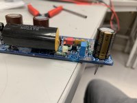
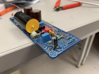
Thanks for all the interest and support for the Alpha Big Boy with Buttah (ABBB) amp! We are almost at 50 boards now. I just verified that the built in solid state relay speaker protection and startup delay circuit works. It works amazingly well. I am really looking forward to this new all-integrated Active Bridge/CRC/CapMx/speaker protection/Alpha amp board come to fruition
The Alpha Big Boy with Buttah (ABBB) 52w Class A Amp GB
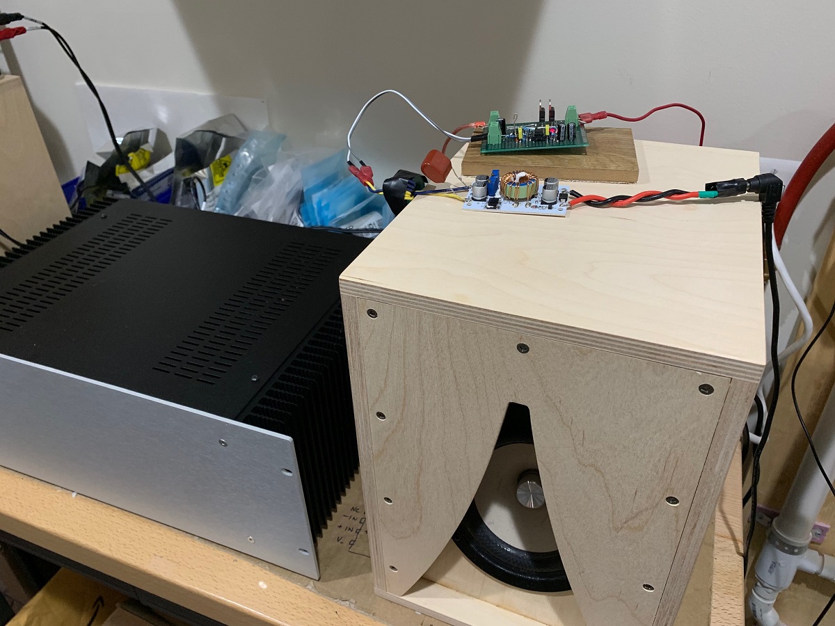
Here was SSR test in action using an M2X and XKi speaker:
The Alpha Big Boy with Buttah (ABBB) 52w Class A Amp GB
Here was SSR test in action using an M2X and XKi speaker:
Xrk,
Can you post more details about this speaker. Sorry for off-topic. Any pointer to the thread will help. Doesn't the front of that speaker look like Karlson aperture?
Thanks
Balaji
Can you post more details about this speaker. Sorry for off-topic. Any pointer to the thread will help. Doesn't the front of that speaker look like Karlson aperture?
Thanks
Balaji
XKi - X's ab initio Karlson 6th Order BandpassCan you post more details about this speaker. Sorry for off-topic. Any pointer to the thread will help. Doesn't the front of that speaker look like Karlson aperture?
Yes, those are XKi's with Tang Band W5-2143 full range drivers. Dimensions are 9in W x 11in D x 13in H (external).
Last edited:
- Home
- Amplifiers
- Solid State
- Aksa Lender P-MOS Hybrid Aleph (ALPHA) Amplifier