Hi Aive,
I would refer you to the GB thread for build questions. It has been a while so I do not remember why I would have bypassed C111? I would go with the schematic of v2 shown at te bottom of Post 1:
Aksa Lender P-mos Hybrid Aleph (ALPHA) Class A Amp GB
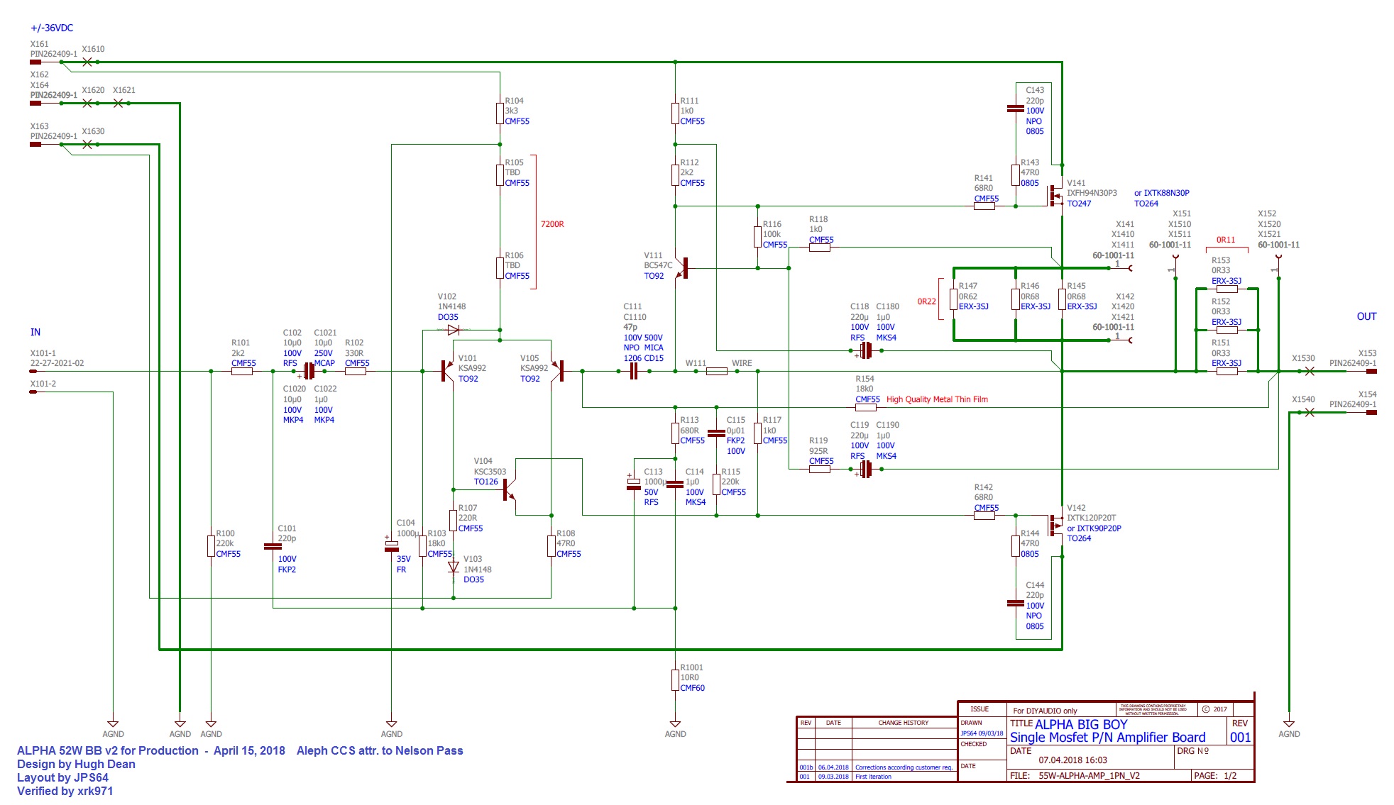
Maybe Hugh recalls what we were doing there - but it seems I have a 22pF cap n parallel with the feedback resistor. Let me go home and look at my build to see what I did. I think what you see there are experiments we were doing on v1 to see what kind of compensation cap should be used there. I would stick with 47pF silver mica.
Perhaps Vunce recalls?
Edit, the search feature was useful. From post:
Aksa Lender P-mos Hybrid Aleph (ALPHA) Amplifier
This was the mod that Hugh said gave extra clarity. You should probably build original amp per schematic first and once working, make this mod. Yes, jumper the cap C111 pins and add parallel cap to R154.
I would refer you to the GB thread for build questions. It has been a while so I do not remember why I would have bypassed C111? I would go with the schematic of v2 shown at te bottom of Post 1:
Aksa Lender P-mos Hybrid Aleph (ALPHA) Class A Amp GB
Maybe Hugh recalls what we were doing there - but it seems I have a 22pF cap n parallel with the feedback resistor. Let me go home and look at my build to see what I did. I think what you see there are experiments we were doing on v1 to see what kind of compensation cap should be used there. I would stick with 47pF silver mica.
Perhaps Vunce recalls?
Edit, the search feature was useful. From post:
Aksa Lender P-mos Hybrid Aleph (ALPHA) Amplifier
This was the mod that Hugh said gave extra clarity. You should probably build original amp per schematic first and once working, make this mod. Yes, jumper the cap C111 pins and add parallel cap to R154.
Last edited:
Never measured distortion at 2.87 volts. I decided to try to compare with your amplifier. Push-pull output stage. My amplifier is not covered by a negative feedback loop. Feedback is only local. The load is also 8 ohms.Gunfu,
This is a single ended Class A amp with an reactive CCS (the Aleph part of it), not a push-pull amp.
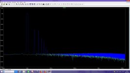
Please enlighten us with what is missing in the model below:
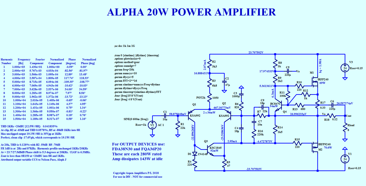
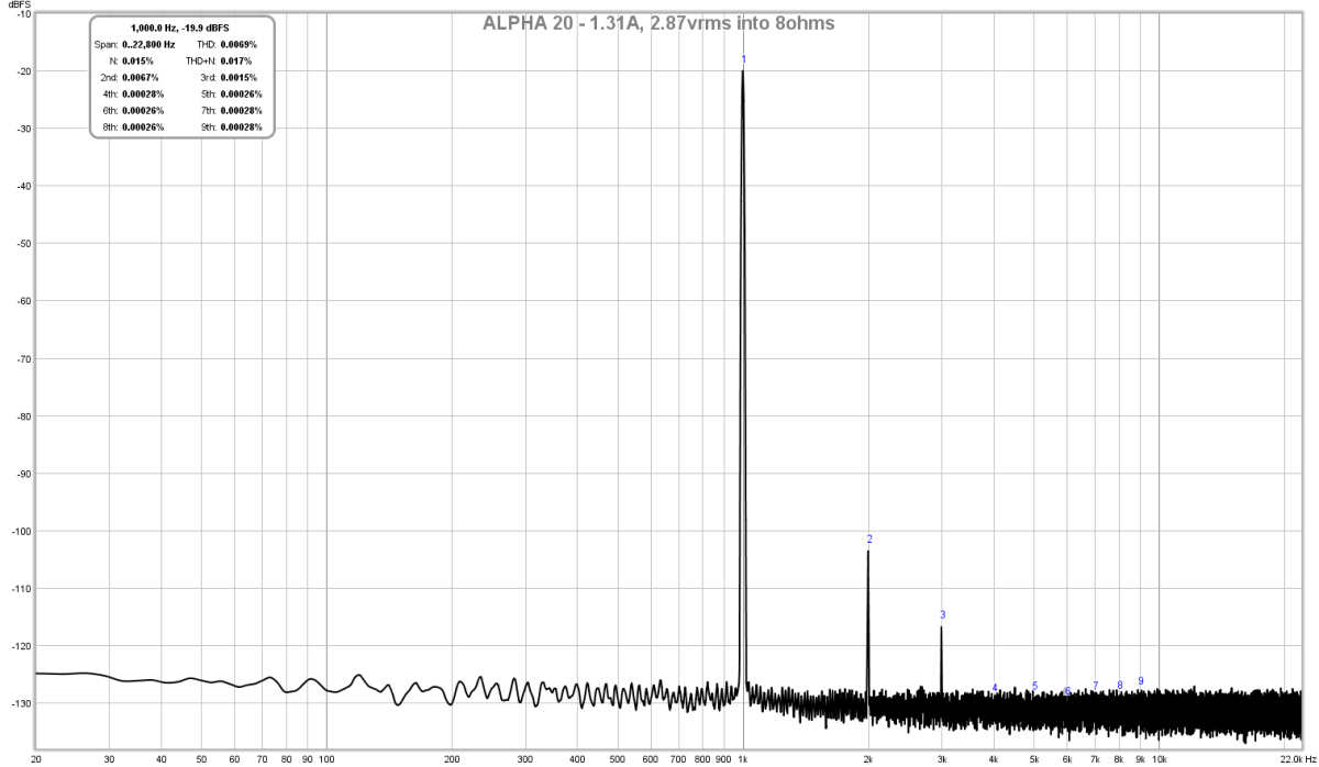
And BTW, the measurements match the model very well - only 2nd harmonic and a little 3rd, no nasty higher 11 and 17 harmonics of any significance.
Attachments
Last edited:
I think you mean, you simulated the distortion in LTspice? My plot is an actual measurement of the hardware. Nice simulation though - but lots of higher order components - albeit they are descending with frequency.
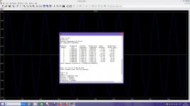
Yes, but if you look carefully and compare with your diagram, you will see that the number of harmonics is 7, not 9 and even the second harmonic and the third and the more the following high-frequency components have a lower level than the noise, for example, in your amplifier -130 dB .
The fourth harmonic has a level of -180 dB, and this is the result for a circuit without total negative feedback.
If I repeat your diagram in LTspice, then the result will exactly match your measurements, I have already checked it repeatedly with different diagrams.
The fourth harmonic has a level of -180 dB, and this is the result for a circuit without total negative feedback.
If I repeat your diagram in LTspice, then the result will exactly match your measurements, I have already checked it repeatedly with different diagrams.
Last edited:
Sounds like your circuit is quite extraordinary to achieve that with no negative feedback! Care to share your schematic with us?
Unfortunately, I can not reveal the scheme and even the idea. But I can say that I made a small discovery based on information from open sources thanks to Bob Cordell and his book, which I read about 20 times. John Kerl from Parasound, who is now working on amplifiers without general feedback. And also thanks to careful modeling on different transistors and various manufacturers of the famous amplifier without feedback The End Millennium from the company LC audio from Denmark.
Special thanks to Analog Devices for the unique free LTspice program.
Special thanks to Analog Devices for the unique free LTspice program.
I think that's Linear Technology that gives us LTSpice, not Analog Devices.
Cool to hear that you discovered a new amp topology. I hope it doesn't have a bizzillion transistors. Let's not compare an open source DIY amp to a top secret state of the art amp that you won't share on the forum, ok?
We have super secret amp designs too, but we just won't even talk about them... 😀

Gunfu,
Rather than hijacking the thread with secret mens business, perhaps you should open your own thread?
There have been many techniques for avoiding global feedback, and a quick study of the history reveals a huge variety of them. Most designers are familiar with many of them and a few are still available as commercial products, such as the Ayre and Pass products.
HD
LTspice | Design Center | Analog DevicesI think that's Linear Technology that gives us LTSpice, not Analog Devices.
If on the forum all amplifiers would have similar characteristics, I would also very much like to lay out my scheme for discussion.
I don't know why, but your 2.87VRMS is -20 dB lower than my 2.87VRMS. This is where the real secret squirrel is hidden.😀😀😀
Last edited:
Analog and linear merged. LT stand for linear technology and spice is Simulation Program with Integrated Circuit Emphasis, which is a common acronym in the industry. It’s a much nicer acronym than Computer Analysis of Nonlinear Circuits, Excluding Radiation... =D
Hi Folks,
We have a new item under development for a GB: a solid state relay (SSR) DC protection and turn-on delay board. The nice thing about this item is that it will be fully professionally assembled and tested. You just need to solder your own choice of speaker connector (spade, Miolex, or flying lead) and it is read-to-run (RTR). More info here:
Ready-to-Run (RTR) SSR DC Speaker Protection and Delay GB
Yes, they are one, but not everything is as simple as it seems. If you take a closer look at their website, you will find: ©1995 - 2019 Analog Devices, Inc. All Rights ReservedAnalog and linear merged. LT stand for linear technology and spice is Simulation Program with Integrated Circuit Emphasis, which is a common acronym in the industry. It’s a much nicer acronym than Computer Analysis of Nonlinear Circuits, Excluding Radiation... =D
Hi Aive,
Edit, the search feature was useful. From post:
Aksa Lender P-mos Hybrid Aleph (ALPHA) Amplifier
This was the mod that Hugh said gave extra clarity. You should probably build original amp per schematic first and once working, make this mod. Yes, jumper the cap C111 pins and add parallel cap to R154.
Just incase we might lead people astray - I checked against the sim and don't believe we should be jumpering across C111 for this mod. Just leave C111 disconnected/unpopulated and install new cap across R154.
The RTR SSR DC protect circuit (prebuilt and ready to run) GB is now open for ore-orders. This is the perfect circuit to go with the Alpha 20 or Alpha BB.
Ready-to-Run (RTR) SSR DC Speaker Protection and Delay GB
Ready-to-Run (RTR) SSR DC Speaker Protection and Delay GB
ABB slowly coming together...

Waiting on some bits and pieces to be delivered, and lots of mechanical assembly to go ><
Waiting on some bits and pieces to be delivered, and lots of mechanical assembly to go ><
Lookin’ good aive!
Maybe use insulated faston connectors for the transformer secondaries. They could short how they are now 😱
Maybe use insulated faston connectors for the transformer secondaries. They could short how they are now 😱
Lookin’ good aive!
Maybe use insulated faston connectors for the transformer secondaries. They could short how they are now 😱
Thanks Vunce - good pickup, I’ll throw some heatshrink on those connectors

- Home
- Amplifiers
- Solid State
- Aksa Lender P-MOS Hybrid Aleph (ALPHA) Amplifier