aive,
Congratulations on getting the amp running. 🙂
You are playing it with the KEF LS50 (the black speaker with the copper color driver in the background)?
Yep - they’ve never sounded so good. I suspect my previous amp is too under powered to drive these properly 🙂
Nominal volts is 37 VDC at output of the SLBs (loaded).
Nominal volts is 37 VDC at output of the SLBs (loaded).
Right on!!
The sense of endless power from the BB is very satisfying 😉
Hi Aive,
Very nice work! Sorry about the mixed MOSFETs - some fuses would have probably prevented the total meltdown. We might have to consider adding fuses at the output of the SLB in the future.
You have one ABB with heatsinks up and another with it down - that threw me for a loop there. Glad that it works well with the SLB - and this basically shows what the ABBB is like, but just more compact and with DC offset and turn on delay SSR built in.
Hi Aive,
Very nice work! Sorry about the mixed MOSFETs - some fuses would have probably prevented the total meltdown. We might have to consider adding fuses at the output of the SLB in the future.
You have one ABB with heatsinks up and another with it down - that threw me for a loop there. Glad that it works well with the SLB - and this basically shows what the ABBB is like, but just more compact and with DC offset and turn on delay SSR built in.
Totally my silly mistake - still not sure how it happened, I was double checking every component before soldering. Must've been tired (that's my excuse) >< Luckily no speakers were plugged in, it was just first powerup on the bench. If I had a variac might've been safe.
Aive,
This is a big project. Any Class A has huge heat output, and small (but large scale) audio power. You are an Adelaide man, so the summers are often over 35C and you will find that this amp is not ideal in that environment. The room will heat, but the sound is exquisite. Coping with the waves of heat on a hot day will test your fortitude; but many in audio consider Class A is worth it.
You will find this amp has it all, SS muscle, with tube grace. It really is one of the best amps I have ever done, I'm sorry I did not come to Class A earlier. It is significant that it is only possible with Nelson Pass' brilliant active current source, one of the cleverest advances to modified Class A I have ever seen.
Hugh
Aive,
This is a big project. Any Class A has huge heat output, and small (but large scale) audio power. You are an Adelaide man, so the summers are often over 35C and you will find that this amp is not ideal in that environment. The room will heat, but the sound is exquisite. Coping with the waves of heat on a hot day will test your fortitude; but many in audio consider Class A is worth it.
You will find this amp has it all, SS muscle, with tube grace. It really is one of the best amps I have ever done, I'm sorry I did not come to Class A earlier. It is significant that it is only possible with Nelson Pass' brilliant active current source, one of the cleverest advances to modified Class A I have ever seen.
Hugh
Was a great project Hugh 🙂 I had a lot of fun and late nights putting it all together - you were right weeks ago, it's a big job but very satisfying 🙂
I couldn't dial up the volume late last night, but plan to have some good listening time this arvo 😛
Oh I'm in QLD btw, which is hot too 😛
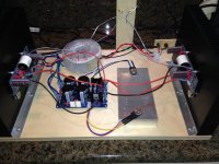
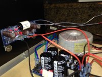
A less messy picture (i was in a rush to power on last night 😛)
Will still be cleaning up and making tweaks for awhile going forward I think - but for now, time to listen to some tunes.

Will still be cleaning up and making tweaks for awhile going forward I think - but for now, time to listen to some tunes.
Curiously - one channel's FETs are ~5deg C higher in temp at the heatsinks compared to the other channel.
Bias measures about the same between channels, 0.6 vs .61 V across R147/46/45. The higher temp channel has the slightly lower voltage oddly enough..
Anything to be concerned about? Could be mechanical/mounting related....
Bias measures about the same between channels, 0.6 vs .61 V across R147/46/45. The higher temp channel has the slightly lower voltage oddly enough..
Anything to be concerned about? Could be mechanical/mounting related....
If your heatsink pressure from clamp bolts is not the same the temps will be different. This is normal - but indicates you can perhaps tighten the bolts a bit or use more evenly spread heatsink paste.
If your heatsink pressure from clamp bolts is not the same the temps will be different. This is normal - but indicates you can perhaps tighten the bolts a bit or use more evenly spread heatsink paste.
Thanks for the tip - a mate also suggested same thing. I’ve tried retightening and the difference has reduced. I just didn’t get the FET mounting heights exactly the same across boards unfortunately.
Back to listening 😛
Thanks for the tip - a mate also suggested same thing. I’ve tried retightening and the difference has reduced. I just didn’t get the FET mounting heights exactly the same across boards unfortunately.
Back to listening 😛
Previously mentioned mate here ...

Got it all hooked up just in time for Fear Innoculum I see!! 😎
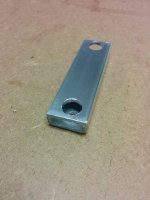
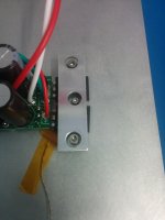
I did a high bias class ab amp (The Wire - LME49830 + lateral mosfets) a few years ago and played around with clamping the fets down in that build. See attached some photos I dug up of the final clamp I used. I was inspired by EUVL's Linear Audio article regarding the design decisions in the F5X chassis
Attachments
Hey Guys
Just wanted to share that I just Built the SLB Power Supply,
Also built a pair of the Alpha 20 boards.
Just fired them up a few hours ago and I must say they
Sound fantastic right out of the gate very smooth with great detail
And surprising Bottom end extension.
I would like to thank X and Hugh for great support on the build.
Attachments
Last edited:
Congratulations Bigaudioscotto!
Another Alpha20 is born 😀
What Antek transformer are you using?
Enjoy your new Alpha20!
Another Alpha20 is born 😀
What Antek transformer are you using?
Enjoy your new Alpha20!
Hello Vunce
I am using Antek 400va 22v.
QUOTE=Vunce;5894887]Congratulations Bigaudioscotto!
Another Alpha20 is born 😀
What Antek transformer are you using?
Enjoy your new Alpha20![/QUOTE]
I am using Antek 400va 22v.
QUOTE=Vunce;5894887]Congratulations Bigaudioscotto!
Another Alpha20 is born 😀
What Antek transformer are you using?
Enjoy your new Alpha20![/QUOTE]
Hello all!
I'd like to report another working SLB/Alpha build - with a few custom tweaks of my own. Special thanks to XRK and AKSA for some debug help that I'd like to report on as well.
If anyone is looking to use different MOSFET devices in their build, you should specifically avoid the IXTH76N25T for the Aleph CCS section. I would also suggest avoiding any of the IXYS Trench-FET products that might be similar to this one. I had originally used that device paired with the IXTH90P10P and went through about 4 of them before figuring out that they were the problem. Immediately on startup they self-destructed shorted across all 3-terminals. Fortunately I was using a dim-bulb tester that protected the fuse 🙄. Without a fused input or dim-bulb tester, this would have quickly destroyed the 0.33ohm power resistor. The PMOS was unaffected.
I decided to finish the build by returning to the venerable IRFP240/9240 pair and can report that they work wonderfully. Temperatures are fine with the absurd amount of heatsinking I have and I can leave my fingers on the transistor mounting washers pretty much indefinitely (<50C). Aluminum oxide insulators and Arctic Silver Ceramique II were used for all mounted devices.
Posted below are some pictures of the build:


In the above pictures you can see the SLB and Alpha boards in the DIYAudio 5U case. Additionally, there's a custom Toroidal soft-start board to prevent the big toroid from occasionally tripping breakers on startup due to inrush from residual magnetism. Each speaker output is also protected with a time-delay and DC protection board that I designed as well (before I heard about XRK's SSR design!) All 3 of these boards are powered from a separate 12VAC toroid that comes up with the main one.
The main modifications are:
The initial test results are shown below:

A Bode plot showing smooth 20dB gain across the frequency range and a nice rolloff starting ~50kHz.

1KHz square wave response showing a clean rise and no ringing.

10KHz square wave response.

Clipping behavior (10x on probes) showing ~48V P-P before clipping with 28VDC +/- supplies.
As a bonus, here's the schematic that I used to implement this version of the Alpha with my own modifications:

The bias potentometer R105 was adjusted to 1052 ohms before installation and I measure 28mV of DC offset after warmup, so no adjustment was needed.
This is quite a wonderful sounding amplifier! I spent the majority of last night into the wee hours listening to a variety of music and nothing I threw at it came close to being more than it could handle. Very articulate and clear with plenty of power for my ~90dB efficient speakers and listening environment.
I'd like to report another working SLB/Alpha build - with a few custom tweaks of my own. Special thanks to XRK and AKSA for some debug help that I'd like to report on as well.
If anyone is looking to use different MOSFET devices in their build, you should specifically avoid the IXTH76N25T for the Aleph CCS section. I would also suggest avoiding any of the IXYS Trench-FET products that might be similar to this one. I had originally used that device paired with the IXTH90P10P and went through about 4 of them before figuring out that they were the problem. Immediately on startup they self-destructed shorted across all 3-terminals. Fortunately I was using a dim-bulb tester that protected the fuse 🙄. Without a fused input or dim-bulb tester, this would have quickly destroyed the 0.33ohm power resistor. The PMOS was unaffected.
I decided to finish the build by returning to the venerable IRFP240/9240 pair and can report that they work wonderfully. Temperatures are fine with the absurd amount of heatsinking I have and I can leave my fingers on the transistor mounting washers pretty much indefinitely (<50C). Aluminum oxide insulators and Arctic Silver Ceramique II were used for all mounted devices.
Posted below are some pictures of the build:
In the above pictures you can see the SLB and Alpha boards in the DIYAudio 5U case. Additionally, there's a custom Toroidal soft-start board to prevent the big toroid from occasionally tripping breakers on startup due to inrush from residual magnetism. Each speaker output is also protected with a time-delay and DC protection board that I designed as well (before I heard about XRK's SSR design!) All 3 of these boards are powered from a separate 12VAC toroid that comes up with the main one.
The main modifications are:
- Higher input impedance (47kΩ versus the original 22kΩ)
- C111 reduced to 45uF allowing the use of a polypropylene film cap with custom bracket.
- Component values adjusted closer to the 4Ω version - 2A bias current should allow 4Ω usage.
- Input sensitivity reduction to allow a higher input voltage before clipping into 8Ω for use with a preamp or hot sources. The final design configuration has exactly 20dB of gain.
- Slightly higher DC supply voltage from using one step up (AS-4225) on the main toroid.
- Snubbers on both NMOS and PMOS (optional, but helpful)
The initial test results are shown below:
A Bode plot showing smooth 20dB gain across the frequency range and a nice rolloff starting ~50kHz.
1KHz square wave response showing a clean rise and no ringing.
10KHz square wave response.
Clipping behavior (10x on probes) showing ~48V P-P before clipping with 28VDC +/- supplies.
As a bonus, here's the schematic that I used to implement this version of the Alpha with my own modifications:
The bias potentometer R105 was adjusted to 1052 ohms before installation and I measure 28mV of DC offset after warmup, so no adjustment was needed.
This is quite a wonderful sounding amplifier! I spent the majority of last night into the wee hours listening to a variety of music and nothing I threw at it came close to being more than it could handle. Very articulate and clear with plenty of power for my ~90dB efficient speakers and listening environment.
Congratulations to the latest builds from aive, bigaudioscotto and raptorlightning !
The Alpha is getting momentum 🙂
I've also started with soldering an Alpha4R.
@raptorlightning : nice report,
the alumina insulators are doing great.
Too bad that the IXTH76N25T didn't work, on paper it has all the correct parameters,
did you also have the snubbers on the Ixys ?
The Alpha is getting momentum 🙂
I've also started with soldering an Alpha4R.
@raptorlightning : nice report,
the alumina insulators are doing great.
Too bad that the IXTH76N25T didn't work, on paper it has all the correct parameters,
did you also have the snubbers on the Ixys ?
- Home
- Amplifiers
- Solid State
- Aksa Lender P-MOS Hybrid Aleph (ALPHA) Amplifier