Mtn View - Listening Impressions #2
After having satisfied my curiosity (somewhat) by building the Aleph J, I have rotated my M2x back into the system. The ability to tinker with different input stages is irresistible for someone like me, so that's what I'm doing. Both amps sound amazing in slightly different ways, so I don't feel like I'm missing out on anything with the M2.
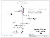
After reacquainting myself with the last version of my Mtn View veroboards, I finally got around to trying some different transistors in the J1 position. (See the attached schematic.) I am already familiar with the 2N4416 JFets from a couple custom effect pedals that I have built. The original version of this transistor came in a small TO-72 metal case, and is said to have been used by Howard Dumble as an extra gain stage at the front end of some of his guitar amps. Linear Systems now offers the 2N4416 in both metal and plastic cases, so I ordered a set of the TO-92 plastic versions to try in the Mtn View. The plastic case version of the 2N4416 has an identical pinout to the J112, so component substitution is very straightforward.
The 2N4416 JFets have a noticeably different presentation than the standard J112. Initial impressions were of an emphasized upper treble, while continued listening settled into simply a more forward sound to each recording. With the best recordings, the 2N4416s brought out the realistic attack and sonic signatures of plucked and percussive instruments, a feature of the Mtn View circuit that I appreciate because it works quite well with my old Vantersteens. However some recordings fared less well from a bit too much of a thing. The J112s might be a more general purpose selection that work fine with a broad set of audio systems and recordings. The 2N4416s, on the other hand, are brilliantly good for those cases where the sound is more laid back to begin with. I can recommend them as an alternate device for those who wish to experiment with tuning the sound of their Mtn View IPS.
I am tempted to add a 15pf to 20pF cap between the Gate and Drain of these JFets to see if that tames their response. After all, my veroboards already commit a couple minor acts of heresy, so why not? For those working with the standard Mtn View PCBs, all of the other circuit modifications are simple component substitutions. The Gate to Drain caps could be soldered on the underside if one wanted to try that.
After having satisfied my curiosity (somewhat) by building the Aleph J, I have rotated my M2x back into the system. The ability to tinker with different input stages is irresistible for someone like me, so that's what I'm doing. Both amps sound amazing in slightly different ways, so I don't feel like I'm missing out on anything with the M2.
After reacquainting myself with the last version of my Mtn View veroboards, I finally got around to trying some different transistors in the J1 position. (See the attached schematic.) I am already familiar with the 2N4416 JFets from a couple custom effect pedals that I have built. The original version of this transistor came in a small TO-72 metal case, and is said to have been used by Howard Dumble as an extra gain stage at the front end of some of his guitar amps. Linear Systems now offers the 2N4416 in both metal and plastic cases, so I ordered a set of the TO-92 plastic versions to try in the Mtn View. The plastic case version of the 2N4416 has an identical pinout to the J112, so component substitution is very straightforward.
The 2N4416 JFets have a noticeably different presentation than the standard J112. Initial impressions were of an emphasized upper treble, while continued listening settled into simply a more forward sound to each recording. With the best recordings, the 2N4416s brought out the realistic attack and sonic signatures of plucked and percussive instruments, a feature of the Mtn View circuit that I appreciate because it works quite well with my old Vantersteens. However some recordings fared less well from a bit too much of a thing. The J112s might be a more general purpose selection that work fine with a broad set of audio systems and recordings. The 2N4416s, on the other hand, are brilliantly good for those cases where the sound is more laid back to begin with. I can recommend them as an alternate device for those who wish to experiment with tuning the sound of their Mtn View IPS.
I am tempted to add a 15pf to 20pF cap between the Gate and Drain of these JFets to see if that tames their response. After all, my veroboards already commit a couple minor acts of heresy, so why not? For those working with the standard Mtn View PCBs, all of the other circuit modifications are simple component substitutions. The Gate to Drain caps could be soldered on the underside if one wanted to try that.
Attachments
As long as you're fooling around with 1970s era JFETs in metal can packages, why not plug in one or two JFETs that don't explode when you apply 45 volts from gate to drain and 45 volts from gate to source? This will let you remove the (nonzero!) impedance of D2 from the JFET drain, and as a result, suffer far less of that nasty Miller multiplication upon Cgd. What's not to like?
_
_
Attachments
input boards and M2X voicing
Has anyone tried putting the various input boards on a rotary switch, so that the M2X can be voiced as one wishes? Reading the post by Tungsten on his work with different resistors and the can vs. plastic transistors, and the associated listening tests is making me think that such a voicing approach may have merit for some recordings over others.
Has anyone tried putting the various input boards on a rotary switch, so that the M2X can be voiced as one wishes? Reading the post by Tungsten on his work with different resistors and the can vs. plastic transistors, and the associated listening tests is making me think that such a voicing approach may have merit for some recordings over others.
Has anyone tried putting the various input boards on a rotary switch, so that the M2X can be voiced as one wishes? Reading the post by Tungsten on his work with different resistors and the can vs. plastic transistors, and the associated listening tests is making me think that such a voicing approach may have merit for some recordings over others.
If you get the urge for a road trip, you could come here and listen to the amp on a pair of ... SH50s.
")
If you get the urge for a road trip, you could come here and listen to the amp on a pair of ... SH50s.
Danley SH50s? I used to put his stuff in my pro and commercial sound system designs.
M2X Mouser Project BOMs
Thought I would share my Mouser BOMs. Norwood is not included (I'm bad w/ SMD). These are PCB components only and no power supply. Each BOM is for building 2 channels.
M2X Amplifier https://www.mouser.com/ProjectManager/ProjectDetail.aspx?AccessID=332e5eadef
M2X Austin https://www.mouser.com/ProjectManager/ProjectDetail.aspx?AccessID=9f59b4cf65
M2X Tucson https://www.mouser.com/ProjectManager/ProjectDetail.aspx?AccessID=c9bad1a6ba
M2X Mtn View https://www.mouser.com/ProjectManager/ProjectDetail.aspx?AccessID=df3c2af01f
M2X Ishikawa https://www.mouser.com/ProjectManager/ProjectDetail.aspx?AccessID=6e2397153a
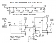
"I suggest that if you’re absolutely certain you’ll never drive M2X with a tube preamp, never ever ever, consider soldering C0 into the amplifier board. C0 is a NP0/C0G ceramic capacitor, 50 volts, 220 pF. Of course you can cut it out later if you change your mind."
Does the B1 KORG triode preamp count as a tube preamp, should C0 be removed if using this preamp?
Does the B1 KORG triode preamp count as a tube preamp, should C0 be removed if using this preamp?
Does the B1 KORG triode preamp count as a tube preamp
The schematic, attached below, might help you decide:
_
Attachments
"I suggest that if you’re absolutely certain you’ll never drive M2X with a tube preamp, never ever ever, consider soldering C0 into the amplifier board. C0 is a NP0/C0G ceramic capacitor, 50 volts, 220 pF. Of course you can cut it out later if you change your mind."
Does the B1 KORG triode preamp count as a tube preamp, should C0 be removed if using this preamp?
I would think not, since it has JFET output buffers.
Finally
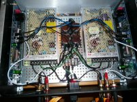
A quick note to indicate that I have actually finished my first Pass amp, after a journey that has lasted since sometime in 2014, with F4 boards and a store chassis. I've since been through the F6, the M2, and now this amp. (Pic below, hopefully)
It's the store Deluxe 4 chassis, the M2X boards, with Ishikawa installed now (long story), two Meanwell LRS 200 power supplies, and a little CLC board to filter and to provide convenient power supply taps. Not shown: The original LRS 350 supplies, which are equipped with fans that make the listening room sound like a computer server farm. Also not shown: me with my head inside the 100db+ horns listening for hum or other noise. There is none.
Got appropriately toasty over an appropriate time period, and I was able to get the offset pretty close to zero, with the originally suggested trim components.
Sounds great, and I greatly appreciate the help of those who have assisted me in the build, especially Donald, my Wisconsin buddy whose similar setup convinced me that this would work.
Attachments
It's the store Deluxe 4 chassis, the M2X boards, with Ishikawa installed now (long story),
Beautiful build! Those SMPSs really filled up the floorspace quickly.
In the lower right we can read the word "Norwood" on the input daughter card, and in the lower left we can see that the input daughter card components are surface mounted. That doesn't sound like Ishikawa to me (?)
Tubes:
I appreciated your first response, telling of the Danleys you have running with this amp. And I really appreciated this last post, on the amps you've done and how you are finding this one, when driving super efficient horns.
Myself, I run a pair of heavily modified K horns, using EV HR6040's driven by Altec 288's on top. And the later model minidsp (had the first gen, too, but this more recent model performs much better for my needs), doing the biamp, time alignment, all the good stuff that digital crossovers do.
I run this using a respected English make mosfet amp for the bass horns and an SET tube amp for the top end.
I have acquired two sets of the M2X boards and components, and the unobtainium parts for the Ishikawa inputs.
So your comments on NOT being in a photo with your head in the mouths of those horns listening for noise REALLY hits me where I live.
Appreciate those posts!
Beautiful build! Those SMPSs really filled up the floorspace quickly.
In the lower right we can read the word "Norwood" on the input daughter card, and in the lower left we can see that the input daughter card components are surface mounted. That doesn't sound like Ishikawa to me (?)
Mark, it is a kind of a long story. I'm sure that there are those who enjoy taking the store chassis apart and putting it back together. I'm not one of them. So I, first, took the (ahem, burned up) old M2 boards out and installed the M2X boards without taking the chassis apart, or the power supplies out. I then got the M2X, with Norwoods, working, but the noise from the power supply fans was way too loud ... for indoor use. So I got the new fanless supplies, and installed them, without taking the chassis apart or taking the boards out. Got the amp biased up and the offset set (note that Mouser ships these power supplies with the voltage selector set for 230v, and that in this amp, I had to unscrew and raise the supplies and slide that selector to the correct voltage, after turning it on and off several times, the whole time wondering who, indeed, was the dim bulb in the equation) and I only had one working channel, where I had originally had two. Concluding that I must have (again) burned something up, and having the parts (from the F6) to build the Ishikawa, I convinced myself that the problem was that I had damaged the left channel Norwood.
I had not. I had merely broken the tiny wire for the left channel input off of the input jack. So today, I redid that connection, using a little heatshrink to make the connection secure. Did I replace the Ishikawas with the Norwoods? I did not, although I will do that when Amazon delivers my set of tiny metric sockets to make that job easier. Without taking the chassis apart. - Pat
Tubesguy, congratulations! Your narrative is filled with delightful truths. BTW these are the just-for-M2x tools which, in my experience, gave the greatest benefit (vs. standard toolbox items) when I built my first M2x. Not in a diyAudio Store chassis but rather in an eBay Chinesium box.
Amazon.com: ATD Tools (575 10-Piece Metric T-Handle Hex Key Set: Automotive
Amazon.com: Pro'sKit 1PK-9402 Hex Nut Driver Set: Industrial & Scientific
H-90 Bourns Inc. | Tools | DigiKey
Amazon.com: ATD Tools (575 10-Piece Metric T-Handle Hex Key Set: Automotive
Amazon.com: Pro'sKit 1PK-9402 Hex Nut Driver Set: Industrial & Scientific
H-90 Bourns Inc. | Tools | DigiKey
- Home
- Amplifiers
- Pass Labs
- The diyAudio First Watt M2x