I will try to lower the VAS current a little as stll is a bit high(5.4mA).
I will try smaller value caps in the same time.
I will try smaller value caps in the same time.
Last edited:
C8, C11=330nf.... Unstable again.
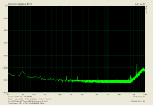
OK leave it without caps, performance does not change much without it.
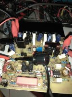
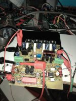
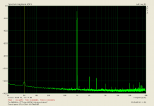
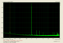
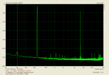
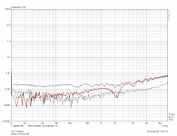
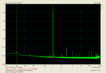
New test.
Power supply linear +/-50v
Bias=136mA
Offset=0mV.
VAS current= 3.8mA
Power supply linear +/-50v
Bias=136mA
Offset=0mV.
VAS current= 3.8mA
Attachments

Last edited:

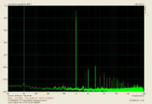

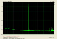
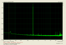
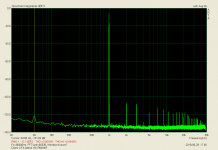
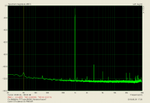
For now, H3 > H2 distortion 😱
Thimios, you are a tireless machine. Surely they must be the Mousakás that you eat.
Thimios, you are a tireless machine. Surely they must be the Mousakás that you eat.
Last edited:
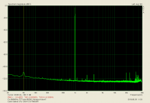
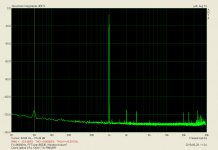
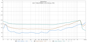
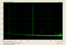
STEPS TEST.
this amp should have better performance
look at to mine, very similar topology but use vertical mosfets and more stable compensation scheme
Attachments
this amp should have better performance
look at to mine, very similar topology but use vertical mosfets and more stable compensation scheme
What is the common point if we speak for a different amplifier and a different test gear? 🙂
this amp should have better performance
look at to mine, very similar topology but use vertical mosfets and more stable compensation scheme
What is point in this, who said that lateral mosfet will generate less distortion then verticals? Laterals have other advantage.
You can open your thread and show your amp.
I don't gave up never! 😎Thinios, tank you, you don't gave up easily.😀
What is point in this, who said that lateral mosfet will generate less distortion then verticals? Laterals have other advantage.
You can open your thread and show your amp.
Yes, and if you want an independent test, you can send me an unassembled pcb and i wii take care😉
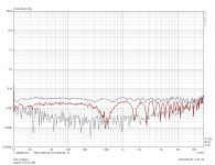
Please see post #251,the sound card loop test.For now, H3 > H2 distortion 😱
Thimios, you are a tireless machine. Surely they must be the Mousakás that you eat.
Testing using a sound card isn't highly accurate, this depends from the sound card's characteristics.
Commercial gear for THD measuring or audio band frequency analyzer is out of mine buget.
We keep some money for Mousakas

Last edited:
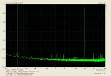
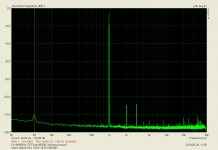
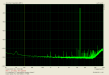
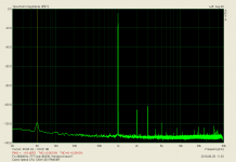
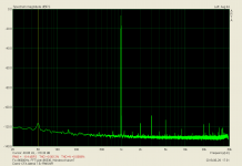
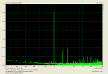
Damir CFA lateral 120W
Driving 4 R LOAD.
Please take into account that power supply is 300VA.
Driving 4 R LOAD.
Please take into account that power supply is 300VA.
Attachments
Last edited:
actual state
hi Damir, hi thimios,
after 2 days of rest from from discussions and and measuring of the prototype build from thimios, i am interested in the actual state of the Lateral CFA 120 BSA ( my name is Black Superb Amplifier; since the pcb has a black mate soldermask).
My planned DC supply is about +/- 52 V. What are the actual pcb modifications, changes in values, additonal equipped parts, parts not to equip? i followed the discussions in the thread, but i am not sure, which is the actual parts list for thimios working prototype.
Damir, BOM of the class A type misses R0= 10R. Is it possible to reduce the LP R1C2 to a smaller frequency, since the 3db-pint is about 1,5 MHz (C2new at 1nF or 2,2nF?)
BR
Günni
- Home
- Amplifiers
- Solid State
- Lateral CFA 120W - BSA