Hi Gunni,hi Damir, hi thimios,
after 2 days of rest from from discussions and and measuring of the prototype build from thimios, i am interested in the actual state of the Lateral CFA 120 BSA ( my name is Black Superb Amplifier; since the pcb has a black mate soldermask).
My planned DC supply is about +/- 52 V. What are the actual pcb modifications, changes in values, additonal equipped parts, parts not to equip? i followed the discussions in the thread, but i am not sure, which is the actual parts list for thimios working prototype.
Damir, BOM of the class A type misses R0= 10R. Is it possible to reduce the LP R1C2 to a smaller frequency, since the 3db-pint is about 1,5 MHz (C2new at 1nF or 2,2nF?)
BR
Günni
I expect Thimios to tell what was last configuration for +-50V PS and then I will suggest BOM changes, or additional caps if needed.
You can increase LP cap, with 1nF 3dB point is around 1.1MHz and with 2n2 around 360kHz but phase shift at 20kHZ is 3.5 deegre.
Increasing LP resistor will increase input distortion and noise. You know that source output impedance is part of that LP filter.
Hi Gunni,
I expect Thimios to tell what was last configuration for +-50V PS and then I will suggest BOM changes, or additional caps if needed.
You can increase LP cap, with 1nF 3dB point is around 1.1MHz and with 2n2 around 360kHz but phase shift at 20kHZ is 3.5 deegre.
Increasing LP resistor will increase input distortion and noise. You know that source output impedance is part of that LP filter.
I will post schematic as built for +/-50v power supply soon.
Regards.
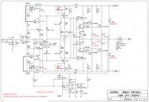
Ok here you are.
It is not necessary to change anything on the pcb, just some resistors values.
R6 and R9 change to 11k and instead of R5 and R10 just use a jumpers.
Understanding it correct , Q5 and Q6 is designed for 2N5551/2N5401 or BC550/BC560 (turned bei 180°), but not for SA992 and SC1845. Anything against the use of 2N5551/5401 or BC546/BC556 or BC550/BC560 (Class A version). C8 and C11 can be used in the Class A versiin (35V DC) ? i have here 330nF and 470 nF Wima MKP4 or should they remain unequipped? Damir, do you agree to the layout issues i sent before? Which layout program did you use?
BR
Günni
BR
Günni
Understanding it correct , Q5 and Q6 is designed for 2N5551/2N5401 or BC550/BC560 (turned bei 180°), but not for SA992 and SC1845. Anything against the use of 2N5551/5401 or BC546/BC556 or BC550/BC560 (Class A version). C8 and C11 can be used in the Class A versiin (35V DC) ? i have here 330nF and 470 nF Wima MKP4 or should they remain unequipped? Damir, do you agree to the layout issues i sent before? Which layout program did you use?
BR
Günni
Nothing against 5551,5401 just i have change those because i can't trust the UTC label especially when looking for the source of oscillation.
It seems that C8,C11 not affect the stability at +/35v
Last edited:
It seems that C8,C11 not affect the stability at +/35v
I hope everyone understand that the 1uF emitter load bypass is what makes Dadod's amp unique and interesting. Without it, I can't see any possibility this will sound as good as my simpler CFA. Could you please try higher capacitance instead of lower? No more than 3.3uF may be?
Tested using 2.2uf,isn't stable.I hope everyone understand that the 1uF emitter load bypass is what makes Dadod's amp unique and interesting. Without it, I can't see any possibility this will sound as good as my simpler CFA. Could you please try higher capacitance instead of lower? No more than 3.3uF may be?
Tested using 2.2uf,isn't stable.
Thx thimios. Dadod, how does the distortion spectrum look like without these caps?
Thx thimios. Dadod, how does the distortion spectrum look like without these caps?
Did you see the fft test?
Did you see the fft test?
Your test? Yes. I need to see simulated version using the same windowing as shown on page one. The exclusion of the emitter bypass capacitors might change the spectrum shape. I like the one shown on page one.
I hope everyone understand that the 1uF emitter load bypass is what makes Dadod's amp unique and interesting. Without it, I can't see any possibility this will sound as good as my simpler CFA. Could you please try higher capacitance instead of lower? No more than 3.3uF may be?
Hi Johnego,
From my perspective, this is the wrong assumption.
Emitter load bypass you mention above is very frequency-dependent, becoming a bypass at rather high frequencies. In the worst case, it may influence the loop characteristics somewhere above 10KHz.
Damir's amplifier has got a good ("short") harmonics profile (mainly harmonics 2, 3), so whatever part of the bandwidth we take, there will be no big difference in the spectrums with or without those capacitors in the frequency range we are able to hear.
Those caps definitely influence stability margins, however, depending on a particular design, they can either increase or decrease them. One of my designs becomes stable as soon as they are in place (small value, 150-220pF). Most of the other designs - become unstable.
I have never experienced any influence on the sound quality from these caps though.
Cheers,
Valery
Those caps definitely influence stability margins, however, depending on a particular design, they can either increase or decrease them. One of my designs becomes stable as soon as they are in place (small value, 150-220pF). Most of the other designs - become unstable.
That's why I mentioned that these caps were problematic. I actually meant to say to remove it. Simulation is not accurate so for this kind of 'compensation' where 'bigger not always better' we have to be careful (and always start without the cap). I used this technique but never for stability compensation. My similar amp has better thd performance but stable with ONLY one cap across FB. Never found such RC technique necessary for stability.
In this amp I guess Dadod wanted a 'wideband' open loop performance so he used those caps. I'm curious myself if it can add something to the sound. If the purpose is only THD20K, I can achieve better without it.
But the thd spectrum on page one is interesting. Mine is not like that and I'm curious to find out what has shaped that hd spectrum. I'm sure it is any of the small/compensation caps. Do you know?
I am at my house, and no PC with me, just laptop, no possibility to simulate. Back home in 20 days.
Soon ready for test
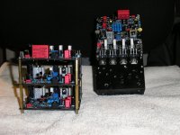
Both versions of the Lateral CFA 120W BSA (Black Superb Amplifier) are soon ready for test. Some capacitors , resistors and the coils still missing and ordered already. i am really excited, how they will sound both.
If someone is interested in remaining empty PCBs, PM me. Due to high shipping costs, only european users will be preferred
Günni
Attachments

I'm curious to see if this oscillation is present using a set of j162, k1058😕
Hi thimios,
i will go for the SK1058/SJ162, i have them both from original Hitachi and Renesas. Lets hope the best.😎😉
Günni


- Home
- Amplifiers
- Solid State
- Lateral CFA 120W - BSA