now i can't see the h.f oscillation but something is wrong again.
33pf//22pf.
There is still oscillation, go back to 22pF.
I don't recognize those ceramics caps, are you sure those are NP0/C0G, even C6?
Do you have caps of higher value then 1nF for caps on the cascode bases, like 3.3nF to 10nF?
I will see tomorrow if any..There is still oscillation, go back to 22pF.
I don't recognize those ceramics caps, are you sure those are NP0/C0G, even C6?
Do you have caps of higher value then 1nF for caps on the cascode bases, like 3.3nF to 10nF?
I have used those many times. Black dots is NPO indication or i'm wrong?
3.3nf or something up to 10nf is need to be NPO too?
Last edited:
I will see tomorrow if any..
I have used those many times. Black dots is NPO indication or i'm wrong?
3.3nf or something up to 10nf is need to be NPO too?
I am not sure, what I am baying lately it's clear yellow or blue, but could be.
Those of higher capacity better to be XR7.
To hear from you tomorrow.
I am not sure, what I am baying lately it's clear yellow or blue, but could be.
Those of higher capacity better to be XR7.
To hear from you tomorrow.
ok,good night🙂
I was thinking what PS voltage increase from +-35V to +-40 V can change in this amp behavior and provoked that HF oscillation and couldn't find explanation.
Thimios, have you checked +-40V PS for oscillation, maybe it comes from it?
Thimios, have you checked +-40V PS for oscillation, maybe it comes from it?
I was thinking what PS voltage increase from +-35V to +-40 V can change in this amp behavior and provoked that HF oscillation and couldn't find explanation.
Thimios, have you checked +-40V PS for oscillation, maybe it comes from it?
Please take in to account that the PS where this amplifier is stable is +/-31v not +/-35v.
When testing in +/-40v, amplifier function exactly as at +/-50v.
In any case i will see if it is any problem with the +/-40v PS.
All PS are a classic linear topology.
Last edited:
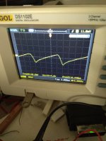
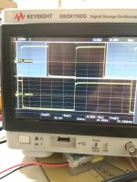
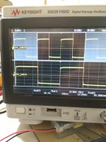
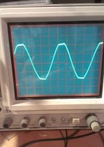
Back to generator test.
I think that is periodicaly stable, not stable.
10nf ceramic multilayer from cascode bases to the gnd.
I think that is periodicaly stable, not stable.
10nf ceramic multilayer from cascode bases to the gnd.
Attachments
Last edited:
I was thinking what PS voltage increase from +-35V to +-40 V can change in this amp behavior and provoked that HF oscillation and couldn't find explanation.
Thimios, have you checked +-40V PS for oscillation, maybe it comes from it?
- Cbc decreases as Vce increases. A high Cbc slows down transistors. This may explain why the amp is becoming more stable at lower supply voltage
- An oscillation coming from power supply doesn't explain the high oscillation amplitude on output. Measure the rails for HF is easy
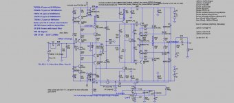
- Cherry compensation C6 is hardly to get stable. I never got it stable.
- Cbc decreases as Vce increases. A high Cbc slows down transistors. This may explain why the amp is becoming more stable at lower supply voltage
- An oscillation coming from power supply doesn't explain the high oscillation amplitude on output. Measure the rails for HF is easy
- Cherry compensation C6 is hardly to get stable. I never got it stable.
I built amps with this compensation and they a stable. Here is not question compensation used (in my opinion) but something else.
I understand that you don't want to change your current compensation scheme and do not want to test if the removal of the cherry cap would help.😱
I agree with Toni here - the Cherry cap may be tricky. I didn't notice it initially.
I would even try a 5-10pF cap, having its right side connected the same way as the right side of C6, but its left side - connected to the NFB junction point (top side of R45).
Instead of C6.
I would even try a 5-10pF cap, having its right side connected the same way as the right side of C6, but its left side - connected to the NFB junction point (top side of R45).
Instead of C6.
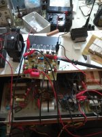
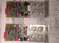
This is the amp with lateras I built and my daughter is using with no problem.
PS regulator from JLH +-55V.
PS regulator from JLH +-55V.
Attachments
Last edited:
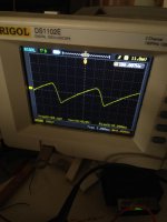
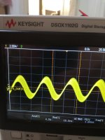
Beside the fact that the scope focus is bad I would say oscillation near clipping.
There was no oscillation, old oscilloscope not possible to focus better.
It is one more possibility that Exicon laterals need higher value gate stopper then original Hitachi I used in my amp, bat I never built an amp with Exicon laterals.
There was no oscillation, old oscilloscope not possible to focus better.
It is one more possibility that Exicon laterals need higher value gate stopper then original Hitachi I used in my amp, bat I never built an amp with Exicon laterals.
The datasheet shows what the gate resistors should be.
The p channel needs a slightly lower resistor value as it is more capacitive.
The datasheet shows what the gate resistors should be.
The p channel needs a slightly lower resistor value as it is more capacitive.
I don't see that in the datasheet of Exicon mosfets, could you show that?
I don't remember where I saw it now but I think resistor values were something like 330r for n channel and 220r for p channel.I don't see that in the datasheet of Exicon mosfets, could you show that?
They also talked about SG zeners to limit the mosfet current and make them almost indestructible.
It might have been an application note rather than the datasheet.
if you think this is an avenue to investigate, it may also be worthwhile to look into Bob Cordell's idea from his old 50W amp of using a series R+C from gate to ground with a much smaller series gate resistance.
he talks about it in his paper available here: http://www.cordellaudio.com/papers/MOSFET_Power_Amp.pdf, upper left side of page 12. i think there's more discussion about the idea on this website somewhere, too.
mlloyd1
he talks about it in his paper available here: http://www.cordellaudio.com/papers/MOSFET_Power_Amp.pdf, upper left side of page 12. i think there's more discussion about the idea on this website somewhere, too.
mlloyd1
There was no oscillation, old oscilloscope not possible to focus better.
It is one more possibility that Exicon laterals need higher value gate stopper then original Hitachi I used in my amp, bat I never built an amp with Exicon laterals.
Good catc Valery!I agree with Toni here - the Cherry cap may be tricky. I didn't notice it initially.
I would even try a 5-10pF cap, having its right side connected the same way as the right side of C6, but its left side - connected to the NFB junction point (top side of R45).
Instead of C6.
I think is the end...
Coming soon.
- Home
- Amplifiers
- Solid State
- Lateral CFA 120W - BSA