Hello all,
what is the quintessence of thimios build of the BSA-120? Any modifications necessary to the published schematics and layouts? a short summary would be helpful.
Günni
what is the quintessence of thimios build of the BSA-120? Any modifications necessary to the published schematics and layouts? a short summary would be helpful.
Günni
Only one modification.Hello all,
what is the quintessence of thimios build of the BSA-120? Any modifications necessary to the published schematics and layouts? a short summary would be helpful.
Günni
Connect R11, R12 (the left side) to +/-15v.
Use lower power supply +/-35v.
I will test this at +/-40v, may be today.
Stay tuned!
P. S I will post all voltage measurements too.
Only one modification.
Connect R11, R12 (the left side) to +/-15v.
Use lower power supply +/-35v.
I will test this at +/-40v, may be today.
Stay tuned!
P. S I will post all voltage measurements too.
I will suggest next modification when you start testing, I want it to work with +-55V too.
I will suggest next modification when you start testing, I want it to work with +-55V too.
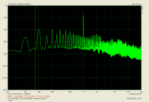
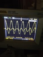
Now is tested at +/-40v.
Unfortunately is unstable again.
Attachments
Last edited:
Now is tested at +/-40v.
Unfortunately is unstable again.
Now is to hot here in Zagreb to think, I will suggest this evening what to try.
Now is to hot here in Zagreb to think, I will suggest this evening what to try.
The same in Greece too!
Don't push yourself in stress.🙂
I don't know if it make sense but i see that is more stable when input signal raise.
Try changing R20 from 1k5 to 330R, all the rest the same?
When testing at +/-50v i has see the same.Try changing R20 from 1k5 to 330R, all the rest the same?
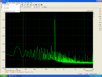
Low level fft shown oscillation but there was an improvement when testing at a higher volume.
I will try this change this afternoon.
Now is tested at +/-40v.
Unfortunately is unstable again.
Input stage DC operation is mostly controlled by the 15v zener. Output stage DC operation is mostly controlled by base-to-base voltage of the driver set by Vbe multiplier through the pot setting. So it is the VAS current that is mostly affected when you increase PS voltage. The transistor is too small, the emitter load bypass cap (1uF) can be tricky sometime. How about lowering VAS current to the same level as when you use lower PS voltage?
BTW, I have experiences where Chinese small signal transistors 'oscillate' at high voltage close to the Vce max. (LTP, Vce=45 or 50, power supply +/-30 or 35 volt)
Last edited:
Input stage DC operation is mostly controlled by the 15v zener. Output stage DC operation is mostly controlled by base-to-base voltage of the driver set by Vbe multiplier through the pot setting. So it is the VAS current that is mostly affected when you increase PS voltage. The transistor is too small, the emitter load bypass cap (1uF) can be tricky sometime. How about lowering VAS current to the same level as when you use lower PS voltage?
BTW, I have experiences where Chinese small signal transistors 'oscillate' at high voltage close to the Vce max. (LTP, Vce=45 or 50, power supply +/-30 or 35 volt)
You are correct about input stage operation, and the current trough coscode transistors Q5 and Q6 change just a little (controlled with the current trough Q1 and Q2 and that current does not change with PS voltage increase) and the VAS current as result increase just a little with increase of PS voltage, and that VAS current does not go over 4 mA and used transistors are not to small for that current.
VAS current is controlled by resistors R5 and R10 mostly.
Last edited:
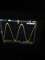
Tested with R20=330R. at +/-40v.
No it isn't stable.
Some information say that 2N5551/5401 tend to oscillate easily in cascodes.
Do you have KSA992/KSC1845 to try instead?
By the way keep 1nF caps at cascode bases.
Some information say that 2N5551/5401 tend to oscillate easily in cascodes.
Do you have KSA992/KSC1845 to try instead?
By the way keep 1nF caps at cascode bases.
There are 546,556 in this position.
I can change with 992,1845 if you want to try.
Last edited:
There are 546,556 in this position.
I can change with 992,1845 if you want to try.
Yes please, be careful different pins positions.
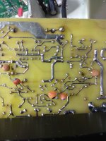
Not stable again.
Ksc1845, ksa992 in cascode and 1nf from bases to the gnd.
Change C9 and C10 to 47pF just to see if helps.
- Home
- Amplifiers
- Solid State
- Lateral CFA 120W - BSA