Glad you got it sorted out and it’s not blowing up now. It was too high of a bias current then.
Power assuming a sine wave signal is P=V^2/R where V is volts rms and R is ohms.
Vrms is Vpp/2.83 (assuming sinusoidal signal). A MOSFET push pull amp loses about 4v off each rail. So that’s 8v from Vpp. +/-63v rails is 126Vpp, minus 8v loss is 118v. 118v/2.83 is 41.7vrms. 41.7v ^2 /8ohms = 1738v^2/8ohms is 217w - assuming clipping doesn’t occur earlier - which you need an OScope to confirm.
Max is 217w - you can do better in some amps that use bootstrapping. It allows swings in Vpp greater than actual rails.
Hope that helps.
This helps immensely - thanks for taking the time to show me the calculation(s) and advising the actual rationale behind it.
This simple shunt regulator can be use with AX amplifiers for preamp supply. Amp rail voltage can be use for regulator input (without 1N4007 diodes and 4700uF caps).
Hi Mr. Mile
In my place i can't find bd241 and db242, can i replace with another transistor ? exp TIP transistor?
Thanks
Regard
Hi Mr. Mile
In my place i can't find bd241 and db242, can i replace with another transistor ? exp TIP transistor?
Thanks
Regard
Use TIP31/32
Anyone can help me to bias the AX14 properly ? Along with the inductor data.
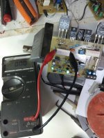
power up the board and connect voltmeter across (parallel) 5W resistor. set the selector to 200mv range and measure the reading. turn the bias pot until you get 15mv reading with no signal input.
AX14 bias
Thanks, that was quicker than I anticipated, can you tell me how many turns the inductor needs and the diameter as well, is there any particular value for the resistor on which the inductor is supposed to be wound on to ?
power up the board and connect voltmeter across (parallel) 5W resistor. set the selector to 200mv range and measure the reading. turn the bias pot until you get 15mv reading with no signal input.
I thought 5200/1943 only recommend 20-30 mAs of bias. with 0.33 resistors that would be 45mA? Shouldn't the mV across the resistor be closer to 8-10mV?
Thanks, that was quicker than I anticipated, can you tell me how many turns the inductor needs and the diameter as well, is there any particular value for the resistor on which the inductor is supposed to be wound on to ?
I don't see an inductor on the AX14 schematic - are you just asking to put it off-board? I typically use 1.0uF (which is 6-8 turns of 1.0mm wire around a AA battery or pen), and a 10ohm 2-3 watt resistor should suffice.
I don't see an inductor on the AX14 schematic - are you just asking to put it off-board? I typically use 1.0uF (which is 6-8 turns of 1.0mm wire around a AA battery or pen), and a 10ohm 2-3 watt resistor should suffice.
Of course there is none on board, but in the AX14 P it's there.
hello every one. i build A40 last week, sounded damn good but the whole project will go way too expensive so i have decided to build A33. i want to feed a33 through p30 preamp. is that suitable ?
besides apex h900, is there anything that can make clas h?
HX11
hello every one. i build A40 last week, sounded damn good but the whole project will go way too expensive so i have decided to build A33. i want to feed a33 through p30 preamp. is that suitable ?
The P30 can feed any stereo amp so yes it will feed the A33.
May I ask, what you mean about the A40 being too expensive? You can use the same PSU with the A40 that you will use for the A33. Even the same heatsink. Since you already have the A40 built, I don't see how building the A33 will save money.
Thanks, Terry
actually transformer is the most expensive part of project. as i will need two transformers one for each module. one transformer costs about 2000PKR so two will cost 4000 one output transistor cost 120 four more transistors 480 more. one pair of 10000uf 100v cap costs 350. for A40 i will need more caps. the A40 that i build was not belonged me.
iam decided to make A33 first then upgrade to A40. A33 can give me 180W per channel easily with one transformer. making a 40 and not getting the power how much A40 can give?
also iam decided to make pre amplifier with input source selector with digital switching.
my be iam wrong at some point
Last edited:
OK I see. I thought you built an A40 for yourself. Nothing wrong with the A33. Beautiful amp.
- Home
- Amplifiers
- Solid State
- 100W Ultimate Fidelity Amplifier