best regards...is it suitable for fh11/ax14?
Yes for any amp
Bullitt,
You are doing everything right and using top components. It may be oscillation then at higher powers. Try increasing C6 to 15pF or 22pF NP0/C0G or silver mica.
Try increasing the large 2W source resistors to 0.68R in an effort to squash it. Change one thing at a time.
You are doing everything right and using top components. It may be oscillation then at higher powers. Try increasing C6 to 15pF or 22pF NP0/C0G or silver mica.
Try increasing the large 2W source resistors to 0.68R in an effort to squash it. Change one thing at a time.
A40+P30 in progres
any suggestion is welcome😎
any suggestion is welcome😎
Attachments
Last edited:
What is the r2 resistor? With capacitor c13 at the output of 10v, I remove the capacitor at the output of 13mv.
1000W +-50V LLC Soft Switching Power Supply / Amplifier PSU Board | eBayNice!
What is the smps?
Is it a diy?
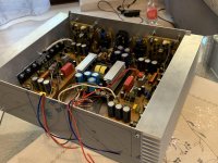
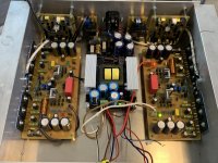
fuego this power supply does not interfere with the boards.
I see that it's not even shielded.
I hope everything is fine.
Great workmanship.
It seems that my A40 will forever remain the most ugly devices in history.))))
I see that it's not even shielded.
I hope everything is fine.
Great workmanship.
It seems that my A40 will forever remain the most ugly devices in history.))))
I too would worry that the PSU is too close to the amp boards without any shielding.
But my big concern is the heat sink fins are horizontal and not anodized - little airflow and little heat radiation...
But my big concern is the heat sink fins are horizontal and not anodized - little airflow and little heat radiation...
Bullitt,
You are doing everything right and using top components. It may be oscillation then at higher powers. Try increasing C6 to 15pF or 22pF NP0/C0G or silver mica.
Try increasing the large 2W source resistors to 0.68R in an effort to squash it. Change one thing at a time.
First thing I tried - changed the washers holding the MOSFETs to the heatsink to 1/8x3/4" and used the #4 washers too, making sure even pressure.
Then I measured the voltages across the Source resistors on BOTH boards to compare - interesting results:
Bad channel - lowest bias setting of 8.5mV on 37V, and 22mV on 65V)
(with +/-38Vdc PSU) measure left to right
--- 8.8 / 8.3 / 8.8 / 8.2 (so pretty equal)
(with +/-65Vdc PSU) measure left to right
--- 22 / 19 / 22 / 20 (again pretty equal) changed DMM and lost decimal
Good channel - can lower bias to 3.5mV on 37V, and 8.5mV on 65V)
(with +/-38Vdc PSU) measure left to right
--- 8.1 / 8.2 / 8.5 / 7.2(???)
(with +/-65Vdc PSU) measure left to right
--- 19 / 18 / 18 / 14 (???)
Measured heat sink (max was 87F) and MOSFET/transitor (max on 95F) temps - nothing went over 100F anywhere I could read a temperature. This was after I ran both amps on the +/-65Vdc PSU for ~30minutes.
I will get you some pictures, but since they both work, I use the same process and it is only the bias trimming that seems short of where I need - I'm fairly confident all the parts are installed and soldered correctly.
So what’s my next option? I changed the source resistors to 0.47r and it has less bias at a higher measured mV across them (35mV across a 0.47= 0.074. Previously I had 22mV across 0.235= 0.094)
Is that still too high of bias?
All this was done with both channels run on same heatsink at +/-65Vdc and same bias on both channels (~75mA) I played loud music for almost an hour and could only get temps up to 115F, which was only during very bass heavy parts - FYI bias would go up to 135mA during these loud bass sections.
Nothing got hot (mostly 90F) except the MJE350 in the middle of the board even with a heatsink it was uncomfortable to touch for more than a five seconds, but only measured 115F on the heatsink.
Also if I cooled the MJE350, the bias would go down, usually ~10-15mV.
Should I try a larger heatsink on it?
I think I am going to just use +/-37Vdc and forego the larger PSU I had planned. I don’t want it to go “pop” after taking all this time to put this amp together. Thanks
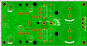
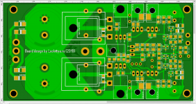
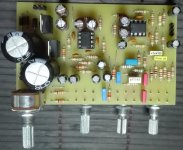
Present to you board Apex AX-17
Nice job - am I seeing it right, you have PSU built in with diodes and supply caps? Cool
So what’s my next option? I changed the source resistors to 0.47r and it has less bias at a higher measured mV across them (35mV across a 0.47= 0.074. Previously I had 22mV across 0.235= 0.094)
Is that still too high of bias?
All this was done with both channels run on same heatsink at +/-65Vdc and same bias on both channels (~75mA) I played loud music for almost an hour and could only get temps up to 115F, which was only during very bass heavy parts - FYI bias would go up to 135mA during these loud bass sections.
Nothing got hot (mostly 90F) except the MJE350 in the middle of the board even with a heatsink it was uncomfortable to touch for more than a five seconds, but only measured 115F on the heatsink.
Also if I cooled the MJE350, the bias would go down, usually ~10-15mV.
Should I try a larger heatsink on it?
I think I am going to just use +/-37Vdc and forego the larger PSU I had planned. I don’t want it to go “pop” after taking all this time to put this amp together. Thanks
If it’s working well now at 37v and seems like it is loud enough for you, maybe leave it alone. I can’t figure out what’s been causing it to blow up either without having the amp in front of me.
If it’s working well now at 37v and seems like it is loud enough for you, maybe leave it alone. I can’t figure out what’s been causing it to blow up either without having the amp in front of me.
Been busy today... tried it out with a single 0.47r source resistor per MOSFET and still couldn't get the bias low enough for me to feel "safe" at +/-65Vdc. Best I could get was ~75mA (35mV across 0.47r)
Google and youtube searches came to my rescue on how to take a too high trimmer and "adjust" to the closer value. Hopefully I didn't break amplifier rules, but it kept coming up on guitar amps, so figure it was worth a try.
I was going to order a 2k trimmer, which @hassan4119 said he used on his version of an APEX amp.
So I took the 5k I had on hand and put a 3.3k resistor across the outside pins to get a 1.9k trimmer.
I can now get the bias down to 0.001 at it's lowest. I set it for 8mV, or ~34mA and I ran it for well over an hour and the heatsink stays at 100F and all the transistors and MOSFETs can have a finger on them for ever without being uncomfortable. Let me know if this is too low, just don't want to create heat if I don't need to.
Any way to guess how much power each channel is producing?
Previously saw you can derive watts from ((voltage*voltage)/(Load*2))
Figuring a couple volt drop at 63*63 = 3,969
so 8 ohm load = 3,969/16 = 248 watts
so 4 ohm load = 3,969/8 = 496 watts
Obviously not 100% efficient, so 80% at 8r = ~200, and 70% at 4r = 350
Is this even close to actual - or a scope the only real way to know?
Thanks for all the help along the way, especially Apex and @xrk971 - really like this simple little amp so far.
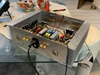
Now on to the other 2 channels and putting it all in a case.
yes, PSU built in with diodes and supply capsNice job - am I seeing it right, you have PSU built in with diodes and supply caps? Cool
Glad you got it sorted out and it’s not blowing up now. It was too high of a bias current then.
Power assuming a sine wave signal is P=V^2/R where V is volts rms and R is ohms.
Vrms is Vpp/2.83 (assuming sinusoidal signal). A MOSFET push pull amp loses about 4v off each rail. So that’s 8v from Vpp. +/-63v rails is 126Vpp, minus 8v loss is 118v. 118v/2.83 is 41.7vrms. 41.7v ^2 /8ohms = 1738v^2/8ohms is 217w - assuming clipping doesn’t occur earlier - which you need an OScope to confirm.
Max is 217w - you can do better in some amps that use bootstrapping. It allows swings in Vpp greater than actual rails.
Hope that helps.
Any way to guess how much power each channel is producing?
Previously saw you can derive watts from ((voltage*voltage)/(Load*2))
Figuring a couple volt drop at 63*63 = 3,969
so 8 ohm load = 3,969/16 = 248 watts
so 4 ohm load = 3,969/8 = 496 watts
Power assuming a sine wave signal is P=V^2/R where V is volts rms and R is ohms.
Vrms is Vpp/2.83 (assuming sinusoidal signal). A MOSFET push pull amp loses about 4v off each rail. So that’s 8v from Vpp. +/-63v rails is 126Vpp, minus 8v loss is 118v. 118v/2.83 is 41.7vrms. 41.7v ^2 /8ohms = 1738v^2/8ohms is 217w - assuming clipping doesn’t occur earlier - which you need an OScope to confirm.
Max is 217w - you can do better in some amps that use bootstrapping. It allows swings in Vpp greater than actual rails.
Hope that helps.
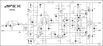
Max is 217w - you can do better in some amps that use bootstrapping. It allows swings in Vpp greater than actual rails.
Like FR150
Attachments
- Home
- Amplifiers
- Solid State
- 100W Ultimate Fidelity Amplifier