Mind you, you only get 20 % of that at their nominal working voltage. X5R multilayer capacitors are extremely non-linear.
Yes, and package size is also a big factor at the same rated voltage:
Temperature and Voltage Variation of Ceramic Capacitors, or Why Your 4.7mF Capacitor Becomes a 0.33mF Capacitor - Tutorial - Maxim
Yep. As MarcelvdG has noted, beware of the horrible voltage coefficient of larger MLCCs unless they are NP0/C0G... but those are becoming available with >100nF capacitance today, even 1uF/50V do exist (at insane prices, though, and MLCCs have become really expensive in general, lately).100 ohms and 1u ceramic perhaps?
Jan
Mind you, you only get 20 % of that at their nominal working voltage. X5R multilayer capacitors are extremely non-linear.
Marcel, thanks for that tip about the reduction to 20%. I'll keep it mind.
Marcel, thanks for that tip about the reduction to 20%. I'll keep it mind.
You can use the Murata SimSurfing tool to verify exact parts and see. It can vary wildly between series and manufacturers.
You can use the Murata SimSurfing tool to verify exact parts and see. It can vary wildly between series and manufacturers.
Thanks, Chris.
PMLCAP?
No voltage coefficient, no microphonics.
Still good ESL/ESR/ D.
Crazy price..
Too big for many applications. Works for coupling, though.
Basically any electroceramic (aka ferro-electric aka piezo-electric) material is non-linear, lossy, microphonic and very temperature sensitive, as the ions move around in the lattice in response to external fields. The reason they are used in the dielectric constants are in the 100 to 100,000 range, rather than the normal 4..10 range for ordinary ceramic materials (in which only the electron distribution moves with external field).
Yes, indeed. For completeness, they age as well. Capacitance goes down by 5 % or so (depending on the type) for each factor of ten increase of the time after the last time they were heated above their Curie temperature. The nominal value applies 1000 hours after heating.
Still, for X5R and X7R, the nonlinearity will usually be a bigger problem than ageing or temperature dependence. The variation over temperature is only +/-15 % worst case. Other types like Z5U really collapse over temperature and are basically only useful around room temperature.
Still, for X5R and X7R, the nonlinearity will usually be a bigger problem than ageing or temperature dependence. The variation over temperature is only +/-15 % worst case. Other types like Z5U really collapse over temperature and are basically only useful around room temperature.
Some time ago, I was surprised to learn that SMD ceramics are available in 22uF and even 47uF values. Just never thought of them as existing in anywhere near such values.
X7R 100nF are good enough.
Yes, indeed. For completeness, they age as well. Capacitance goes down by 5 % or so (depending on the type) for each factor of ten increase of the time after the last time they were heated above their Curie temperature. The nominal value applies 1000 hours after heating.
Still, for X5R and X7R, the nonlinearity will usually be a bigger problem than ageing or temperature dependence. The variation over temperature is only +/-15 % worst case. Other types like Z5U really collapse over temperature and are basically only useful around room temperature.
Marcel, for 15V supply decoupling, a nominal 1u 50V ceramic (not COG/NPO) should be OK except at 200C down a drill hole, no? Or would you advice a .22u film instead? Both are small; I usually put them underneath the IC footprint close to the pins.
Disclosure: some time ago someone gave me a 2000-piece reel of 1u/50V XR5 1206 size ;-)
Jan
You lucky one !Disclosure: some time ago someone gave me a 2000-piece reel of 1u/50V XR5 1206 size ;-)Jan
You can use the Murata SimSurfing tool to verify exact parts and see. It can vary wildly between series and manufacturers.
TDK's search-by-characteristics page is extremely useful. Down the bottom in the 'advanced search' area there's a DC bias box. You plugs in your working voltage and your target capacitance range - it'll find those caps which fall within your target value range at the voltage you're using. I sometimes find a smaller value cap delivers more uF at the voltage of interest than a higher-valued (and more expensive) one.
Search by Characteristics | Capacitors - Multilayer Ceramic Chip Capacitors | TDK Product Center
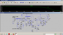
The only downside i can see with any op-amp i used in simulation is the ringing around 1...2Mhz, but i can't hear anything wrong in my real player. Any idea how could be that reduced in the most effective way?Either Spice is totally wrong, or I missed something .... Distortion is not better than using 2x opamp in parallel. So where is the benefit ?
Cheers,
Patrick
Attachments

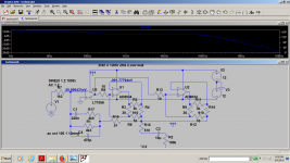
It seems that you only need a higher speed fet input op amp as a second op-amp.So the outlined idea here:
https://www.diyaudio.com/forums/analog-line-level/155143-class-aa-opamp-schematic.html#post1987545
and in the original Burr Brown app note is valid in any composite op-amp unless you really take measurements and compensate as Groner (or ad797) did inside the loop.
https://www.diyaudio.com/forums/analog-line-level/155143-class-aa-opamp-schematic.html#post1987545
and in the original Burr Brown app note is valid in any composite op-amp unless you really take measurements and compensate as Groner (or ad797) did inside the loop.
Attachments
Last edited:
Marcel, for 15V supply decoupling, a nominal 1u 50V ceramic (not COG/NPO) should be OK except at 200C down a drill hole, no? Or would you advice a .22u film instead? Both are small; I usually put them underneath the IC footprint close to the pins.
Disclosure: some time ago someone gave me a 2000-piece reel of 1u/50V XR5 1206 size ;-)
Jan
Yes, from -55 to +85 degrees C that X5R decoupling capacitor should work fine. Its capacitance will probably be somewhere between 500 nF and 1 uF. For example, this Taiyo-Yuden capacitor would have a capacitance of about 600 nF at 15 V, 25 degrees and 1000 hours:
https://nl.farnell.com/taiyo-yuden/umk316bj105kd-t/ceramic-capacitor-1uf-50v-x5r/dp/1853564?st=1uF 50V X5R 1206
^ Jan, I'd be using those X5R's up as well; especially if your layouts allow you to get the 1206 package tight to your opamp pins, the lead inductance *should* be quite modest and serve you well as a wide bandwidth local bypass cap. Given most all DS's give a recommended 100 nF, even with de-rating you'll be a bit higher. The bigger worry will be the inductance side of things, and layout can mitigate a lot of that vs smaller packages.
I do plan to use them up, probably die first ;-)
I always place one direct between the Vcc and Vee pins of the package footprint, bottom side. That seems to work well.
I've gone away from placing decoupling caps between Vcc/Vee and ground, never good to couple ground stuff into the supplies. In very low distortion circuits, that sometimes gives unexplainable (for me) higher-than-expected distortion.
Whatever is of it, my current method works fine. So far.
Jan
I failed only putting them to Vcc-Vee. Vcc-GND-Vee plus Vcc-Vee was needed for lowest noise in my case.
It's the way almost every cassette player decoupled the tape head op-amps...you don't want the power ground next to your IC die, just the signal ground or the shield .I always place one direct between the Vcc and Vee pins of the package footprint, bottom side. That seems to work well.
Jan
- Home
- Source & Line
- Analog Line Level
- Samuel Groner's super opamp