Alice, Bob, Carol, Dave .....
Once upon a time long ago, I put a circuit schematic into a CAD system and used its layout editor to create a PCB. I clicked the "Connectivity Error Checking" button and the CAD system told me: No hookup errors, the PCB layout exactly matches the schematic. Feeling relieved, I sent the files to a PCB fab house and got my boards back in a few weeks.
But the circuit didn't work.
Eventually I traced it down to a schematic error. Somehow the schematic editor had let me make a T-intersection between a horizontal wire and a vertical wire, without electrically connecting the wires. They were two different "nets" / two different circuit "nodes". The PCB perfectly matched this erroneous schematic so the PCB was a perfect implementation of an error.
I was angry. The CAD system fooled me into thinking everything was okay, and I determined to never let this type of non-connection error happen again.
So I decided to give every node in the schematic a name myself, and not allow the system to assign them (no more "Net_1447003" anonymous nodes for me!). Now I can do a quick eyeball scan down the netlist and make sure that all nodes have human-created names. If I ever see "Net_1447003" then I instantly know it is a schematic error. Aha you basxtard CAD system I caught you!
Thus I got into the habit of naming every node. Saved my buttt a few times so it was worth the small extra effort. Sometimes I do it alphabetically like Alice, Bob, Carol, Dave and so forth. It's an old habit and hard to get rid of, even though I don't use that CAD system any more and even though the one I use now (KiCad) seems relatively bug free.
Mark,
Great story, thanks for sharing and completely logical. Besides, whenever you get an inkling to teach the vagaries of audio electronic design, you can use these names and readers will automatically know which part of the schematic you are talking about. I would encourage others to do the same, it will help newbies in fostering an understanding of how and why the circuit works the way it does. I also highly encourage interested individuals to buy the Art of Electronics by Paul Horowitz. It's an eminently suitable book for an EE undergraduate. I love my copy!
Best,
Anand.
Eventually I traced it down to a schematic error. Somehow the schematic editor had let me make a T-intersection between a horizontal wire and a vertical wire, without electrically connecting the wires. They were two different "nets" / two different circuit "nodes". The PCB perfectly matched this erroneous schematic so the PCB was a perfect implementation of an error.
Wayne has always used the schematic/pcb error checking on his software,
and I never bothered, preferring to minutely examine pcb artwork.
Our error rates were similar for some years, but lately he has pulled
ahead. Prototype PC boards have gotten cheap and quick, so I
just whip them out and let the actual circuit show me thej error of my ways.
😀
Patrick / ItsAllInMyHead,
If I were you I would set my power supply for 46 volts and, if it has current limiting, set the current limit pretty low, like 40mA. Apply the positive lead to Pin3 (including the milliammeter) and the negative lead to Pin1. Read the current. I would leave the other pins open and floating.
Why 46 volts? Because the middle of the acceptable supply range for M2 and M2x, is +23V and -23V. Thus 46 volts end to end.
What should the milliammeter say for Norwood at 46 volts total? Somewhere between 8mA and 30mA. If you want to double check these numbers, the mfr datasheets for the two ICs each give a Supply Current specification (range), and you can calculate the current drawn by the bias resistors R1 and R2 using ordinary algebra.
Patrick / ItsAllInMyHead,
If I were you I would set my power supply for 46 volts and, if it has current limiting, set the current limit pretty low, like 40mA. Apply the positive lead to Pin3 (including the milliammeter) and the negative lead to Pin1. Read the current. I would leave the other pins open and floating.
Why 46 volts? Because the middle of the acceptable supply range for M2 and M2x, is +23V and -23V. Thus 46 volts end to end.
What should the milliammeter say for Norwood at 46 volts total? Somewhere between 8mA and 30mA. If you want to double check these numbers, the mfr datasheets for the two ICs each give a Supply Current specification (range), and you can calculate the current drawn by the bias resistors R1 and R2 using ordinary algebra.
Hi Mark,
That makes perfect sense (now). I appreciate both the concise answer and the opportunity to learn a bit more along the way.
Once I get it all hooked up and measured, I'll post back with what I estimated I'd get for Norwood along with the values for all the boards using 46V including Norwood. I'll hold off until I get the sockets for Tucson and do them again all at once.
Thanks!
I got the DIP-8 sockets for the Tuscon and installed the OPA604AP, so I ran the checks again for all the boards at +46VDC using pins 1 and 3. Pin 3 positive and Pin 1 negative.
I set the current limit at 0.040A.
Edited with content removed that could potentially mislead others. I may have had my leads reversed from pins 1 and 3. Rechecking.
Fun stuff. It’s a bit out of my comfort zone, but a few things are starting to emerge from the haze.
I set the current limit at 0.040A.
Edited with content removed that could potentially mislead others. I may have had my leads reversed from pins 1 and 3. Rechecking.
Fun stuff. It’s a bit out of my comfort zone, but a few things are starting to emerge from the haze.
Last edited:
I triple confirmed that I was connecting all the boards the same way at each measuremetn per Mark's suggestion. I stuck a piece of tape on the lead going to pin 3. Because both of the leads were black (from DMM and DC Supply) and very similar alligator clips, I wanted to be very sure I didn't have them reversed for any measurements.
Below are the readings +- 0.1mA
Tucson - 8.7 and 8.7
Mountain View- 28.8 and 28.8
Ishikawa - 7.5 and 7.5
Austin - 11.6 and 12.1
Norwood - 15.8 and 15.9
WHEW!
All of these were taken with the output voltage of the supply at 46V at constant voltage. +- roughly 0.1mA. Some of the boards seemed to “settle” much more quickly than others.
The other thing I learned is that my DMM has a burden voltage of 0.1uV/uA at that current range. So, even though I carefully set the voltage to 46.00V prior to applying the voltage, I was actually putting slightly less voltage to the boards depending on the current. Still learning.
I’m still reading up on how to translate the output current (or other appropriate spec) for the AD744 into a supply current. The HA-5002 clearly lists the range of 8.3mA typical to 10mA max supply current. Fun stuff.
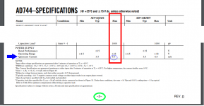
Different companies use different words or phrases to express similar ideas. Here is how Analog Devices describes and tabulates the expected supply current on their AD744 datasheet.
_
I had looked at Quiescent current, but I was not sure if I wanted the current with no load / idle or the max current (output current shorted). I thought it may be somewhere in the middle of the two.
There are so many similar terms, supply current, output current, quiescent current. To a noob, I looked them all up, but whether they can be interchanged seems to be based on the application and the circuit. All a bit <whoosh> over my head for the moment. Don't want to swing the thread to EE for noobs.
But again, and again... thanks!
I just ordered OPA1611 opamps for Tucson input boards. I could only get Texas Instruments version. Is this as good as Burr Brown? …..or does Texas Instruments own Burr Brown so it is same "hardware"?
I also ordered 0.38 mm solder for the surface mount. I will try to see if it is possible to solder using hot air and this thin solder. I have a hot air station where temp and amount of air can be adjusted. Never used it before so have to practice a little first.
I watched this video:
YouTube
But my system is far from this….as I will use just thin solder and not solder paste. But nice to get some inspiration. Always something you can learn from it. Also think he is trying to sell a product 🙂
According to Wikipedia
Both 6L6 and I found it straightforward to build Norwood SMD boards, using a soldering iron + "wire solder" (i.e. not paste) + a magnifier. I showed my exact setup in post #2003 of this thread, if anyone's interested.
In September 2000, Texas Instruments acquired Burr-Brown for $7.6 billion USD.
Both 6L6 and I found it straightforward to build Norwood SMD boards, using a soldering iron + "wire solder" (i.e. not paste) + a magnifier. I showed my exact setup in post #2003 of this thread, if anyone's interested.
Does Burr-Brown still exist as company inside Texas Instruments so you can say the OPA1611 was developed by Burr-Brown?
I have to develop some SMD solder skills so using SMDs is not a limiting factor. If I am able to direct hot air very local so I don't overheat the component then I will try using hot air + wire solder in first place to see how it goes. I have got the holder you suggested. Very cheap…..but seems to do the job.
We can see that using partly SMDs some very nice small circuit PCBs can be made. It must have some positive effects on audio quality as signal path gets very short with all the benefits this gives.
The 26-27 AWG solder I ordered was:
63/37 (Tin, Lead), 183 C
62/36/2 (Tin, Lead, Silver), 179 C
Interesting if the 4 C lower melting point makes a difference. There is a difference in price. Silver is only there to lower the melting point.
63/37 (Tin, Lead), 183 C
62/36/2 (Tin, Lead, Silver), 179 C
Interesting if the 4 C lower melting point makes a difference. There is a difference in price. Silver is only there to lower the melting point.
If you are using wire solder, then I would recommend using a soldering iron with a 0.8mm fine tip. Apply a small amount of flux to the pads on the PCB first, then position the component using a fine tipped set of anti-static tweezers. A bamboo skewer can be used to hold the part in place while the first lead is soldered. You only need a small blob of solder on the tip, not the solder wire for the first pin. Check the position, and then use wire & soldering iron for the remaining pins.
Hot air guns are mainly used for components with solder paste or factory applied solder balls, such as small BGAs. They are also very useful for removing SMD components that have already been soldered on the board. I wouldn't recommend trying to use the hot air gun with wire solder.
Hot air guns are mainly used for components with solder paste or factory applied solder balls, such as small BGAs. They are also very useful for removing SMD components that have already been soldered on the board. I wouldn't recommend trying to use the hot air gun with wire solder.
Thank you for the recommendations. I will practice different methods. I have put a couple of 0.4 mm Weller PT tips in the basket. Which flux do you use? ….the thick brown vaseline stuff or the liquid you can buy in an e.g. 10 ml "pen" (quite expensive compared to the "brown stuff")? ….think I have a small can of the brown stuff but never used it. Think it is something you dip the tip in so probably not good for SMD 🙂
I didn't remember the size of my soldering tip correctly. The one I've been using for SMD is 0.6mm. Both the 0.4mm and 0.2mm tips should work well too.
I've been using the small bottles of MG Chemicals Rosin Flux, usually applied with a small-tipped cotton swab. A while back I picked up some solder flux and paste in small syringes, but haven't used either of these yet. Saving those for the SMD Mosfets that I'll eventually be using to build some 'ideal' bridge rectifiers. It's important to clean the board very well with alcohol after the soldering is done. Then inspect the solder joints carefully with a magnifier to ensure there are no solder bridges, and that each pin was wetted properly with the molten solder.
I've been using the small bottles of MG Chemicals Rosin Flux, usually applied with a small-tipped cotton swab. A while back I picked up some solder flux and paste in small syringes, but haven't used either of these yet. Saving those for the SMD Mosfets that I'll eventually be using to build some 'ideal' bridge rectifiers. It's important to clean the board very well with alcohol after the soldering is done. Then inspect the solder joints carefully with a magnifier to ensure there are no solder bridges, and that each pin was wetted properly with the molten solder.
I have propanol which I use for cleaning. It also seems the Flux is mostly propanol. Then is also contains "Rosin" which is also the stuff which often is in the wire solder. I wonder if I clean first using propanol and the wire solder contains "Rosin" I should be on the "safe side"? .....but anyway......a 10 ml Flux pen may last in many years if it does not "evaporate" during time 🙂
Austin IPS - Listening Impressions
I recently built a pair of Austin IPS boards and installed them in my M2x. Prior to these, I have been listening to my version of the Mtn View input stage.
My first impression was "Wow! There's the full sound stage!" Compared to the Mtn View and Tuscon SMD, both of which are sound stage champs, these surprised me with their sheer presence and detail. The tonal balance is essentially the same as the voltage source regulated Mtn View, but with a more forward presentation regarding the placement of instruments and other sound effects. (Even things like a little hum from from the guitar amp used in the studio have their place in the mix.) Acoustic instruments are very lifelike, and vocals hang in space right where they are supposed to be. Musical involvement is wonderful as well. My first listening session began after the amp had been warming up for over an hour and finally ended four albums later.
Returning to the amp the next morning, I noticed it had settled down slightly. This is typical of the various IPS builds that I've done so far. The Austin didn't seem particularly bright during the first session, but had smoothed out and become slightly less forward the next morning. I'm in the habit of leaving my amps on 24 hours a day, so I don't have to endure the 20 minutes to an hour of warmup necessary if I get the urge to listen to an album. So far, these boards sound just right, and in some ways similar to the Mtn View. Percussion instruments and plucked strings have a slightly different character between the two, however. My preference depends on the particular recording. The Mtn View is remarkable on percussion instruments in general, but the Austin seems to do a better job with their placement in cases where the recording as a whole really shines. Interestingly enough, the Austins are somewhat forgiving of a couple problematic recordings which I still happen to like.
The Austins are going to stay in the amp until I finish reworking my modified Ishikawa prototypes*. I built the Austins using all the recommended transistors, and just substituted a 4.7 uF ceramic cap at C5 between VCC and VEE. I don't have any desire to do any experimentation with this design, as I can't think of anything that might improve it. Unusual for me. Looking at the design, however, has given me some ideas to explore with some of my other builds.
*My veroboard Ishikawas suffered a setback due to a placement / construction error. I had to order another set of PunkyDawg's finest, as I'm afraid the P-types got fried.
Last edited:
Austin, moreso than the others, would greatly benefit from lower thermal resistance, ThetaJA. The Super E-Line package from Zetex is good but maybe you could find or create something even better. Either explicit aluminum TO92 heatsinks like AAVID 5752, or ghetto DIY sinks {glue xitors to US quarter-dollar coins?}, or the very hard to find "Tall Boy" TO-92 packages designed to drive dot matrix print heads, might offer non-negligible amounts of improvement.
_
_
Attachments
I can't find the schematic and BOM for Austin.
I was not in the .zip file I downloaded a while ago (with schematic and BOM of all the other PCBs).
There is a link after the description of Austin in the beginning of the thread for more info.....but this link seems not to go to the right place?
Where to look?
I was not in the .zip file I downloaded a while ago (with schematic and BOM of all the other PCBs).
There is a link after the description of Austin in the beginning of the thread for more info.....but this link seems not to go to the right place?
Where to look?
- Home
- Amplifiers
- Pass Labs
- The diyAudio First Watt M2x