Mile, my problem isn't the trimmer sensivity but the high bias setting by me.Difficult setting due to resistors absence.Bias setting is very sensitive, you can use 220R pot in series with resistor instead 1k.
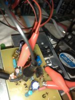
Finally i have add a 18R/5W resistor in series with the positive supply and i measure the voltage to calculate the current.
After bias setting this must be shorted.
In any case you will be surprise when i post results
Terry this pcb must be more robust especially into the mosfet area, use bigger (fat) traces.I was checking my layout to the schematic and I was missing the connection between V+ and the 1k2 and 4007. I have added it here. These should be correct. now. Sorry for any inconvenience.
Bimo, because i know nothing about simulation can you inform me what are the alternative parts?My modification.
This amplifier have high THD for my taste, but have good harmonic profile. Slew rate is high enough.
Thanks all of you for your interesting!
PS. who can answer what is the absolutely maximum bias setting that is safe?
Last edited:
Bimo, because i know nothing about simulation can you inform me what are the alternative parts?
Thanks all of you for your interesting!
PS. who can answer what is the absolutely maximum bias setting that is safe?
My modification using bias servo, so it safe to set bias current high, but I recommended bias current is 150mA for compromise good THD and efficiency.
Maybe you can ask Prasi to make PCB layout.
Please post the spice file for others to experiment !
Here you go.
Attachments
Mile, my problem isn't the trimmer sensivity but the high bias setting by me.Difficult setting due to resistors absence.
Finally i have add a 18R/5W resistor in series with the positive supply and i measure the voltage to calculate the current.
After bias setting this must be shorted.
In any case you will be surprise when i post results
Terry this pcb must be more robust especially into the mosfet area, use bigger (fat) traces.
Bimo, because i know nothing about simulation can you inform me what are the alternative parts?
Thanks all of you for your interesting!
PS. who can answer what is the absolutely maximum bias setting that is safe?
Hi Thimios,
I did enlarge the power and output traces. I didn't think the gate needed more. I will try to populate tomorrow and give mine a go. I plan to use an ammeter on V+ to set the bias. Wish me luck.
Blessings, Terry
My modification.
This amplifier have high THD for my taste, but have good harmonic profile. Slew rate is high enough.
This is really not the same amplifier. Many more parts.
This is really not the same amplifier. Many more parts.
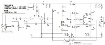
Please can you post the schematic?In any case as it, i don't think that is a high THD that is audible and the gole is to keep amplifier's character.
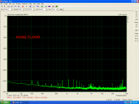
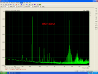
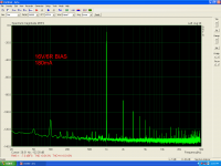
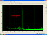
high bias test
Power Supply=+/-50v
offset about 7mV
Idle current about 280mA OR More... be carefull,not safe!
Input current=3mA
VAS current=4mA
VAS transistor=2sc3902.
Power Supply=+/-50v
offset about 7mV
Idle current about 280mA OR More... be carefull,not safe!
Input current=3mA
VAS current=4mA
VAS transistor=2sc3902.
Attachments
-
 IMG_20190531_102056.jpg497 KB · Views: 678
 -
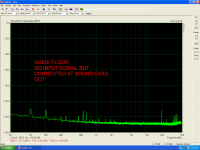 NOISE FLOOR.PNG100.4 KB · Views: 133
 -
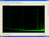 IMD2.PNG98.8 KB · Views: 114
 -
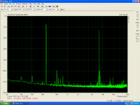 IMD.PNG93.2 KB · Views: 126
 -
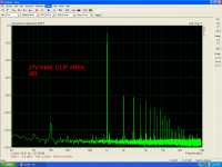 27V.PNG98.1 KB · Views: 127
 -
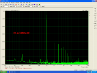 25.4V.PNG95.2 KB · Views: 125
 -
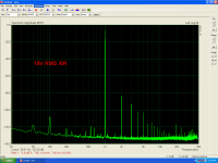 19V.PNG94.5 KB · Views: 638
 -
 8.5V.PNG95.1 KB · Views: 619
 -
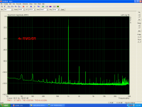 4V.PNG97.1 KB · Views: 637
 -
 2.8V.PNG94.9 KB · Views: 691
Last edited:
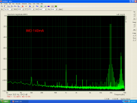
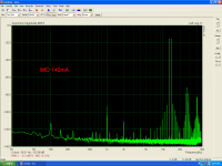
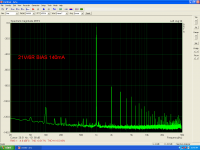
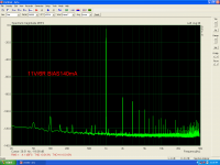
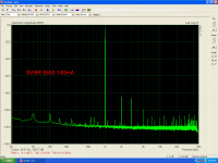
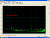
bias 140mA
BIAS=140mA.
BIAS=140mA.
Attachments
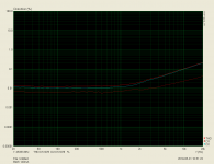


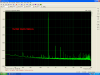

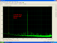
Testing this on a real 3way speaker
In this test a real 3 way speaker used as load.
Bias=50mA
I must run this last test again because another, different divider, was used.
I hope that all these will be useful....
I would like to dedicate this work to a very good friend from Belgium who made me an incredible donation
He does not want his name to be published.
Attachments
Last edited:
In this test a real 3 way speaker used as load.
Bias=50mA
I must run this last test again because another, different divider, was used.
I hope that all these will be useful....
Great great work....
anyone want to try the CFA version? non ltp input stage?
Can you give a brief explanation of what it is?
Thanks
Power Supply=+/-50v
offset about 7mV
Idle current about 280mA OR More... be carefull,not safe!
Input current=3mA
VAS current=4mA
VAS transistor=2sc3902.
Set VAS current to 6mA
Please can you post the schematic?In any case as it, i don't think that is a high THD that is audible and the gole is to keep amplifier's character.
Attachments
Set VAS current to 6mA
I just use minimal bias on my 240/9240 amps.
Connect a speaker.
Turn bias to zero.
Apply signal, monitor output on scope.
Turn up bias until cross over distortion goes.
Simples.
Peavey use a similar method as they prefer lower bias currents.
Ok i will try this soon.
I have try 5mA VAS current just now(4k7+4K7)but THD increased.
I will post the results latter.
Bias=50mA.
Last edited:
I have try 5mA VAS current just now(4k7+4K7)but THD increased.
I will post the results latter.
Bias=50mA.
Replace 3k3 resistor with 4k7
- Home
- Amplifiers
- Solid State
- MOSFET Amplifier IRFP240/IRFP9240