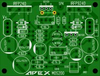
I like the output devices closer to the edge to get onto the heat sink with less bending. But that's just me, this should be fine.
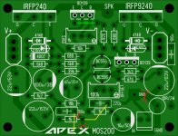
There is no CCS in MOS200, you must replace 18k with 12k for +/-35V, and 6k8 with 4k7. DC offset can be set with 47k, use 100k trimpot instead 47k and set offset...
Last edited:
I added a trimmer for offset and moved the outputs closer to the edge. Had to add one jumper.
Attachments
Hm, what i have up to now....?
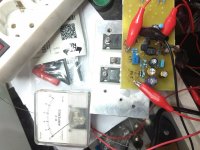
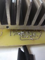
A burned pair of Mosfet and a smoked speaker,when one side of power supply, (+/-50v)disconnected by accident.
More details soon.
A burned pair of Mosfet and a smoked speaker,when one side of power supply, (+/-50v)disconnected by accident.
More details soon.
Last edited:
IRF... "GCE" silk, left over from a IGBT design? 🙂
Add some rail clamp diodes, protection ckt maybe could have saved the speaker. I hope it was a junk/test speaker.
I smoked my amp too, 2 pairs of MJL3281/1302 as I did not have a proper heatsink. All in the name of science.
Was it one of those quick connects? that I dis-like, because I think they are cheap and unreliable, the contacts loose grip after only a few insertions. I like terminal blocks instead, more expensive but you get what you pay for.A burned pair of Mosfet and a smoked speaker,when one side of power supply, (+/-50v)disconnected by accident
Add some rail clamp diodes, protection ckt maybe could have saved the speaker. I hope it was a junk/test speaker.
I smoked my amp too, 2 pairs of MJL3281/1302 as I did not have a proper heatsink. All in the name of science.
Ridiculous crocodile clips. 
Yes, it is a cheap speaker but i haven't many..
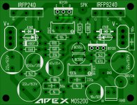
The unpopulated side is the other channel.
Yes, it is a cheap speaker but i haven't many..
The unpopulated side is the other channel.
Last edited:
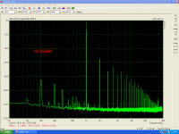
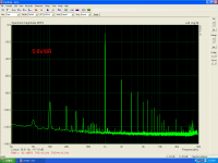
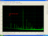
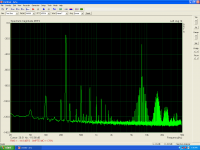
Mosfet Amplifier test.
+/-50v
idle=20mA
I don't think that is good measurement amplifier....
IMD is the highest ι've ever measured!
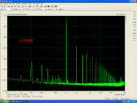
+/-50v
idle=20mA
I don't think that is good measurement amplifier....
IMD is the highest ι've ever measured!
Attachments

Last edited:
Is this high indermodulation as a matter of input gnd and power gnd mixing?
I see that Mile's pcb use a separate configuration.
I see that Mile's pcb use a separate configuration.
Is this high indermodulation as a matter of input gnd and power gnd mixing?
I see that Mile's pcb use a separate configuration.
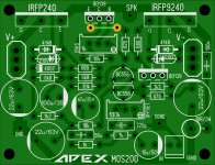
Input and feedback gnd must be separate from power gnd.
Attachments
Sorry about that. I copied the layout from post #1126. Here is a layout with the ground separated and the outputs closer to the edge. It also has a trimmer for adjusting the offset. If you want PDF for etching or photo resist let me know.
Blessings, Terry
Blessings, Terry
Attachments
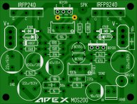
Sorry about that. I copied the layout from post #1126. Here is a layout with the ground separated and the outputs closer to the edge. It also has a trimmer for adjusting the offset. If you want PDF for etching or photo resist let me know.
Blessings, Terry
1k feedback resistor must be connect to input (signal) gnd and power gnd close to 10R/2W resistor.
Last edited:
1k feedback resistor must be connect to input (signal) gnd and power gnd close to 10R/2W resistor.
How does this look?
Attachments
- Home
- Amplifiers
- Solid State
- MOSFET Amplifier IRFP240/IRFP9240