D200.2
hi there i had my D200.2
it work after several tries... i had notice some problem when i turn the volume higher at about 25VAC on output it "ploops" a big DC voltage more likely about 2-3VDC. does anybody had the same problem or knew the root of such problem please help me out...thank you sir mile and others i've got my first class D amp.
regards
SAM
Attachments

hi there i had my D200.2
it work after several tries... i had notice some problem when i turn the volume higher at about 25VAC on output it "ploops" a big DC voltage more likely about 2-3VDC. does anybody had the same problem or knew the root of such problem please help me out...thank you sir mile and others i've got my first class D amp.
regards
SAM
Core material?
Well its an idea, they are more robust, but alas the output resistance is not low, they switch a lot slower than MOSFETs, and the output isn't even linear, so not really suitable for class-D, except perhaps for very high voltage high impedance applications. The MOSFET output characteristic of being close to a pure resistance in the milliohm range is ideally suited for class-D.hi, every one,
Can we replace mosfet with IGBT in d200?
Thank you evry one
IGBT's have an output saturation voltage that varies with current, typically rising to 1.5 to 3V at full output, leading to higher losses and fundamental non-linearities.
When used at kV or so they would come into their own as this output saturation voltage is much less of a percentage, and they are more robust at these voltages.
But you'd only be able to use for sub-bass as the switching frequency would need to be in the audio range - not an easy fask to filter that out!!
D200.2
i have tried several but most of them heated up...
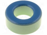
the one that has tolerable temperature was same size as T106- i took it from salvaged HP ATX PSU color green/blue with 62turns of #18AWG magnet wire
thank you sir mile,
sam
Core material?
i have tried several but most of them heated up...
the one that has tolerable temperature was same size as T106- i took it from salvaged HP ATX PSU color green/blue with 62turns of #18AWG magnet wire
thank you sir mile,
sam
Attachments
i have tried several but most of them heated up...
the one that has tolerable temperature was same size as T106- i took it from salvaged HP ATX PSU color green/blue with 62turns of #18AWG magnet wire
thank you sir mile,
sam
Hi
i think this core is working in 350KHZ in original type
CORE type
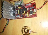
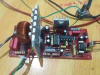
hi sir i have 2 of these cores and 3 of these yellow/white core same size all from trash, btw here's my final D200.2
hi sir i have 2 of these cores and 3 of these yellow/white core same size all from trash, btw here's my final D200.2
1. nobody share Gerber Files for order PCB online
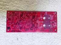
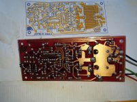
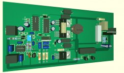
Last week I was off had much time,....this is the reason I have spend time to make new D200 PCB with much SMD components
have a look @ PCB before I will finished
have add Load resistor and flyback diodes MUR460 from output to + / - rail if the amp clips
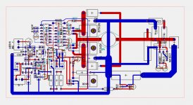
2. APEX add some extension in D200 schematic red marked,
additional NPN resistor, capacitor and negative - 5V
does somebody add and test it ?
I cant fine any DIY Members report, who have build D200 with this extension
Last week I was off had much time,....this is the reason I have spend time to make new D200 PCB with much SMD components
have a look @ PCB before I will finished
have add Load resistor and flyback diodes MUR460 from output to + / - rail if the amp clips
2. APEX add some extension in D200 schematic red marked,
additional NPN resistor, capacitor and negative - 5V
does somebody add and test it ?
I cant fine any DIY Members report, who have build D200 with this extension
Attachments

Crest Add at IR2110 between VB / VS and Mosfet Gate
Bi-directional P6KE20CA
Transient Voltage Suppression Diodes
"The P6KE Series is designed specifically to protect
sensitive electronic equipment from voltage transients "
Is it worth to add this ?
look red marked PIC at D200 ?
Bi-directional P6KE20CA
Transient Voltage Suppression Diodes
"The P6KE Series is designed specifically to protect
sensitive electronic equipment from voltage transients "
Is it worth to add this ?
look red marked PIC at D200 ?
Attachments

i tried to upload the file, in the video was SMPS. that problem at the end of the video exists even on torroid or other PSU tests...
on the pictures were sample of core i used.
Did you fix the problem ?
it looks like we not get responce for problems ?
This thread is 7 years old and long
It should be important to make a Summary about
details to build this amp
getting information through 7 years replys and 118 pages text
is very tedious and unhelpful
Last edited:
Post #1152 schematic from apexaudio is incomplete
load resistor is missing and flyback diodes from load to +/- rail
in this case DC output without load
about additioninal NPN there is no information about benefits
There is no Final schematic available,
no general linformation about recommended output filters and mosfets after 7 years thread
it's like playing roulette in casino to build class D and get surprise
Im not study electronics in University, never working as engineer,
Im only a sales Managaer but many years sales PA and DIY I know the what to do.
Its hard to finished final reliable amp and test, without access to all semi
easy to finished amp and test when stay in China Shenzen / Guangzhou
take metro and can buy all materials and test for try and fail
Last edited:
Post #1152 schematic from apexaudio is incomplete
load resistor is missing and flyback diodes from load to +/- rail
in this case DC output without load
about additioninal NPN there is no information about benefits
There is no Final schematic available,
no general linformation about recommended output filters and mosfets after 7 years thread
it's like playing roulette in casino to build class D and get surprise
Im not study electronics in University, never working as engineer,
Im only a sales Managaer but many years sales PA and DIY I know the what to do.
Its hard to finished final reliable amp and test, without access to all semi
easy to finished amp and test when stay in China Shenzen / Guangzhou
take metro and can buy all materials and test for try and fail
hello mr.
people here might be busy then we have to wait for some response.
yes w/o diode i observed 4VDC on output you need to put load to make it work.
neither am i was not an electronic too.
with +/- 45VDC i barely got 100watts 4R load before the relay on speaker protect activated
that 100watts was enough for home use though.
yes it does not solve the problem coz it will still spikes DC at high volume...
maybe thats the reason why a lot of designers switched to TD class amps.
hello mr.
yes it does not solve the problem coz it will still spikes DC at high volume...
maybe thats the reason why a lot of designers switched to TD class amps.
can you give me more detail information about spikes ......
I not have build amp yet
Class TD is fine,
but in todays time maximum power efficiency is important thing and only Class D is the solution
Next Evolution will be Class D with GAN Fets, because more efficiency
Hi all! I have some dumb question. I would like to build the D200 amplifier for my speakers which are actually rated for 80W with 8R of resistance. Could i build the schematic in post number #1158 (Class D Amp with LM566, LM393 and 2XIRF530 sorry, I do not know how to change link text) with a supply voltage of 24V + 24V out of the transformer?
Also could someone point me out the equation to calculate the power delivered to the speaker given a supply voltage? (I know the Ohm's law and the relation P=V*A but i tried to make some calculation and it does not give the same power as rated by that amplifier project or other projects). I am at early stages with analog electronics especially for power calculation. I am much more at ease with digital electronics😀
Also could someone point me out the equation to calculate the power delivered to the speaker given a supply voltage? (I know the Ohm's law and the relation P=V*A but i tried to make some calculation and it does not give the same power as rated by that amplifier project or other projects). I am at early stages with analog electronics especially for power calculation. I am much more at ease with digital electronics😀
Hi all! I have some dumb question. I would like to build the D200 amplifier for my speakers which are actually rated for 80W with 8R of resistance. Could i build the schematic in post number #1158 (Class D Amp with LM566, LM393 and 2XIRF530 sorry, I do not know how to change link text) with a supply voltage of 24V + 24V out of the transformer?
Also could someone point me out the equation to calculate the power delivered to the speaker given a supply voltage? (I know the Ohm's law and the relation P=V*A but i tried to make some calculation and it does not give the same power as rated by that amplifier project or other projects). I am at early stages with analog electronics especially for power calculation. I am much more at ease with digital electronics😀
I would not recommended, schematic is incomplete
load resistor, flyback clip diodes,.....missing
no gerber files available, you can get finished PCB for 5 USD ftom PCBWAY
I have stop
Build D4K5 its same amplifier, complete without missing imprtant things
gerber PCV files available finished PCB start from 2 USD
Thank you a lot for your advice. I am realizing now that maybe the D200 is not the simplest circuit to be an introduction in the audio and analog world. I will surely start building playing with the D4K5 in the next weeks.
Thank you a lot for your advice. I am realizing now that maybe the D200 is not the simplest circuit to be an introduction in the audio and analog world. I will surely start building playing with the D4K5 in the next weeks.
Look here, D200 V/S D4K5
YouTube
its basically the same amp without missing important additions
IR2110 / IR2113 need Buffer
will work without buffer with 1 pair mosfets too
D200 no have buffer, not good idea, amp will work with 1 pair TO 220 mosfets but ....not do it
Crest CD 3000 have 1 pair Mosfet and use buffer for IR 21xxxx too
- Home
- Amplifiers
- Class D
- Class D Amp with LM566, LM393 and 2XIRF530