@redjr,
Here's a great deal on 60uF polyprops (while they last):
ASC 60uF 500Vdc LTI 4-5 Series Capacitor
Greg in Mississippi
Greg - Thanks for the tip and link. I may have to pick up a couple.
Just out of curiosity I cobbled together a linear supply for the LiFePO4 board. I was running it with an old Acer laptop switching supply. I was pretty surprised by the positive gain in smoothness and a slightly darker background. I realise that this might be more to do with the switcher's influence on the local mains conditions and its effect on my power amp rather than the isolated Pi stack, but in any case the switcher is not getting connected again...
As Greg's signature says...Everything matters.
A switching ps connected to the same wall socket as the rest of your audio equipment is a bad idea, this will inject a lot of HF distortion into your amplifiers.
I connect the switching ps to a separate wall outlet on a separate ps rail/fuse.
I do not know if the switching ps does inject distortion into the battery ps.
@Studley. Not sure what you mean? The board needs DC to operate its control systems and provide charging for the batteries, I also use the board's non isolated 5V out for powering the Pi. I got the rig going with the laptop SMPS and replaced it with the linear supply. Since the Pi is isolated from the DAC by the FiFoPi you could be forgiven for thinking you should be immune from noise from the LiFePO4 board power supply, but as I alluded to and @supersurfer has explained you have to consider all paths of noise transmission. I run my power amp with DC blocking and some fairly gentle filtering on the AC power. I feel that's the best compromise balancing dynamics against noise immunity for me given my resources. (That's a whole other can of worms.....!) The laptop supply could still sneak past the defences and do some damage though. I just thought it was useful to point out that just because Ian's stack is very well isolated from power supply pollution doesn't mean the rest of my system is. That's precisely why I was curious to see what effect eliminating the SMPS would have.
Last edited:
Sorry I was talking bollocks - I haven’t started to put mine together yet and so was just assuming you could run it disconnected once the batteries are charged up. Understand where you are coming from re the smps feeding noise via the mains etc. I use a James Audio conditioner. The guy behind it is a scientist who specialises in reducing electrical noise in all sorts of critical situations. He’s not allowed to talk about half the work he’s done as he’d be breaking the official secrets act . . .
Just powered mine up for the first time and the ESS controller scrolls the intro screen then just hangs on "ESS Controller......" with the dots filling in from the left hand side. On closer inspection there's a pin missing in the ESS controller board GPIO socket and a couple of the other look pretty badly soldered by eye.
I assume all the pins on the GPIO block are meant to be present?
I assume all the pins on the GPIO block are meant to be present?
Or a battery supply to power the battery supply, trying it later.
You know what I’m going to say . . . . 😜
@redjr & @markw4, good comments on the merits of different caps. I shared a picture of the nude Wima with Mark. Mark shared that based on the picture and his description of extended foil construction, it appears at least the MKP2 are of that type. Of course, until we tear down an MKS4, we can only guess... but I bet it is too.
@redjr, I got several of them to try myself... that price is hard to ignore. AND especially being 600V caps, I have a number of options of places to use them.
Mark, on the filtering on the output stage of your 2nd modified DAC, is that what is documented in the OSB.rtf build document in your thread?
@jacklee, thanks for a great exploration into the use of the Dexa Neutron Star 2 clocks with the FiFoPi for best sound. AND the great how-to on how to connect the enable functionality via optocouplers. A great how-to that anyone should be able to follow!
Now I need to try a setup with only one clock to see if there are improvements as your experiments suggest.
Greg in Mississippi
Mark, on the filtering on the output stage of your 2nd modified DAC, is that what is documented in the OSB.rtf build document in your thread?
Basically. There is a schematic in the construction package at: Dropbox - Output Stage Instructions.zip
We also use an opamp-based power supply for ES9038Q2M AVCC. Interestingly, the new AKM current output dac, AK4499, evaluation board will be using discrete opamp-based regulators sort of similar to Jung-Didden for their equivalent of AVCC. No LDO's for analog circuits if at all possible, although they seem fine for digital.
Still haven't tried output voltage resistor loading to ground with ADM7150. I am hoping someone else will beat me to it. 33-ohms should draw 100ma, seems like maybe a good number to try for a 600ma (maximum) part.
@simon dart,
Interesting report on powering your setup vial the LiFePO4 supply via SMPS versus linear charging supplies. My thoughts on this have to do with SMPS leakage, as discussed at length on the Audiophile Style (formerly Computer Audiophile) forums by John Swenson and Alex Crespi in reference to their LPS-1/1.2 Ultracap power supplies. A major reason John developed that supply was to prevent SMPS leakage from flowing into the final USB interfaces and from there into the DAC. He describes 2 types of leakage... the more commonly known low-impedance leakage, which his Ultracap supplies block very well. And a formerly unknown (as far as he could determine) high-impedance leakage which did cross the turn-on/off devices he used (low capacitance transistors as opposed to relays in Ian's supply). The fix for that was to have the negative side of the energizing supply connected to ground, which they implemented in the SMPS energizing supply provided with their LPS-1.2 version.
Though the relays Ian uses will not transmit either of those types of leakage, there still is definitely one path and possibly a 2nd in his supply. The definite path is the 5V supply. Simon, you might re-try that SMPS again with the negative side grounded and see if that improves the performance. That won't stop the low-impedance leakage, but will stop the high-impedance type. You could also try another good 5V supply on the RPi and compare the sonics with the SMPS and linear supplies into the LiFePO4 supply.
The possible path has to do with some of the protection features Ian built into the supply. If you review the manual, you'll see that you can enable/disable a start-up current protection feature. UNLESS Ian implemented this across optocouplers, the connections used to detect the turn-on current will provide a path for the SMPS leakages.
While linear supplies also have some level of leakage, it is MUCH lower than from SMPS's. That's why I built a set of linear supplies to energize my LPS-1/1.2s AND use a linear power source for Ian's LiFePO4 supply.
As I had mentioned in the main thread for this supply, I use this currently-on-closeout linear supply from Jameco:
MKD66123400: Arndt : 40.8W AC-to-DC Unregulated Linear Table-Top Power Supply 12V 3.4A : Power Supplies & Wall Adapters
It is a good option for others in North America with 120VAC power and you can't beat the $8 closeout price. Better hurry, only 263 left in stock!
In a related vein, to get the best sound from the 5V supply, I modified that raw DC supply with:
- Shottky diodes (MBR40250G)
- a larger filter C (UCC KYB 8200uF/25V)
- an AC filter C (Epcos/TDK 2.2uF/450 polyprop)
- and a John Swenson transformer ringing snubber (330R in series with .022uF C) across the transformer secondary
However, even with those mods to the raw DC, I still preferred the sonics with my standard RPi supply over the LiFePO4's 5V supply powering the RPi... better bass, dynamics and a bit better definition. I use a modified K&K Audio 12watt low voltage supply.
I should be clear the sonics with the LiFePO4 supply's 5V supply are not bad... just bettered by my standard supply. So unless you already have a very good 5V supply for the RPi, don't worry.
@misterdog, interesting idea powering Ian's LiFePO4 supply with another battery. Just be aware it charges those LiFePO4 cells at a pretty stout rate and will drain anything but a SERIOUS battery (think car battery) pretty quickly. Of course, if you use an AC-connected supply to charge the cells, swap in your battery supply for listening, then turn it off and immediately swap back in the AC supply, that should work ok and not overly drain your battery. Hmmm... I need to try this!
Greg in Mississippi
@Markw4,
Thanks, that is the doc I have.
I definitely like your level of filtering on the IV stage, which is about 4x what Ian did in his IVStd and not quite 2x what Allo did in their Katana's I/V stage. As I said earlier, I need the greater filtering in my setups to prevent getting ringing in my ears listening to digital gear. Allo's Katana's single-ended output just achieves this in the final configuration with the cascaded filtering of the I/V stage, the balanced-to-single-ended summing stage, and the final single-ended filtering. I've been experimenting with different filter cutoffs in Ian's various I/V & output stages and am getting close to what works for me. AND what I'm using in the I/V stage of the IVStd is very close to your output stage's I/V filtering.
Greg in Mississippi
Why?
What does that do & provide?
& is that the same as using the apodizing filter in the ES9038Q2M?
Greg in Mississippi
What does that do & provide?
& is that the same as using the apodizing filter in the ES9038Q2M?
Greg in Mississippi
Okay, time to go to the next "level". Pretty straightforward. Just need to triple-check all connections for shorts and polarity.
Wires are Duelund 20awg tinned-copper. Solid-core wire is probably easier to handle but I have the Duelund on-hand.
Need run-in before any observations can be made. Too many options too little time.
Good job. I see u are powering the DAC bypassing the ldo using 3 different batteries (because u have 2 power board)
What happens in your opinion if I'll do the same but with only one battery?
May I obtain the same advantage ?
Last edited:
me too in the past ....not bad the ess ones but no pre ringing low post and good antialias filter is better :Minimum phase apodizingI need the greater filtering in my setups to prevent getting ringing in my ears listening to digital gear.
H I F I D U I N O: WM8741 Digital Filters
@paoloilpizzo,
Actually not bypassing LDOs. In the original configuration all three power rails are still powered by the same 3.3V rail from the single input power terminal. The breakaway mini-board contains capacitors for decoupling between the three rails.
I separately powered the three rails using three battery supplies with great results. Initially I also removed the decoupling capacitor mini-board but I found that putting it back is even better.
As this mod needs three 3.3V rails, a single battery board works only if one uses transformer I/V output (which does not need power rail). That way one can configure all 4 rails in the battery board to 3.3V: one for fifopi, and three for the DAC. Otherwise there aren't enough 3.3V rails for that.
Also, you may want to experiment with the decoupling caps for the three rails as that will likely impact the sound, especially for the rail powering AVCC (the analog section).
....I still preferred the sonics with my standard RPi supply ...
What are you referring to as your 'standard RPi supply'. Inexpensive SMPS wall wart? Other?
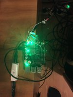
First test of the FIFOPI, and how to play 768Khz over I2S?
I tested connecting the FifoPI via an AudioGD I2S->HDMI to my AudioGD R2R7 DAC.
For software I use DietPI, I stream using HQPlayer on my laptop to the HQplayer network audio adapter on the PI. To power it I used a 5V lineair power supply, which I split into a signal to the PI, and a doubly quieted down 5V via two iFi DC iPurifier 2's.
My previous setup is a PI -> USB -> Singxer SU1 -> I2S -> DAC. This sounds really good. The first impression with the FIFOPI was immediately good. Not yet as detailed or quiet as with the Singxer solution. However it did sound more neutral, and it already sounds spacious.
This is with the standard clocks. I have ordered Accusilicon 90/98 clocks, so that will make the comparison more fair. Also, my current test setup is quite messy in terms of cabling, which cannot contribute to the sound.
So far then, especially for the price, really good!
I also have a question, I have checked with the maker of my DAC that it supports 768Khz. I am also going to install the Accusilicon clocks so the FifoPI can play it. However, I cannot find an I2S driver for DietPI that will let me output it. I tried several drivers, including the I-sabre driver, since that chip supports 768khz, but it will only try to output 384Khz at maximum.
Does anyone you know of a way to output I2S at 768Khz in DietPI? Or any other OS for that matter?
Attachments
- Home
- Source & Line
- PC Based
- IanCanada's Latest RPi GB Goodies Impressions... and your tweaks, mods and hints...