I have this circuit as well. It is for voltage output dacs. It is very good. I used it with akms and ess. SQ depands on the quality of cap used. I used Jantzen Alumen 10uf, but one could use lower value and even better quailty e.g.: 2.2uf Mundorf Supreme EVO Oil Silver Gold. Eventually Super V/I has been replaced with Teramoto Finemet, which so far are the best for me!
The finemets are over $1000 a pair, right?
Too rich for me.
The finemets are over $1000 a pair, right?
Too rich for me.
Yep. However once I calculated how much is spend on alternatives: opamps, discrete opamps, other trafos, class A dual -/+15V supplies, good quality caps etc. I realized that I can sell it, add couple of bucks and get those trannies.
Yep. However once I calculated how much is spend on alternatives: opamps, discrete opamps, other trafos, class A dual -/+15V supplies, good quality caps etc. I realized that I can sell it, add couple of bucks and get those trannies.
Good point. But it is easier for me to spend $100 at a time, spread over some months, than $1000 all at once, since I'm cheap lol.
Another question is how much better are the finemets? I know this is subjective, and difficult to answer. But are we getting into the area of diminishing returns?
On the other hand, if they are that much better, this could give me incentive to sell some stuff I really should sell, and put the money towards finenets.
Randy
Another question is how much better are the finemets?
What does that question even mean?
The reason I ask is because different people seem to have different tastes in sounds they prefer. Among the very high end crowd, a small bit of carefully tuned 2nd and 3rd harmonics (with nothing above the 3rd) seem to be favored over lowest possible distortion and noise. Transformers can be used to give that tiny bit of 'good' distortion, or they can be used to create larger amounts of low order distortion to help mask other remaining high order distortion in a system. It is probably generally best to get distortion as close to zero as possible, then season slightly. It is easy for distortion to get cloying, even though at first a bit more than the minimum can seem or feel very nice. One test a high end audio designer I know uses is how long one can listen to a piece of gear in a system without wanting to go do something else instead. If a system will keep him listening interest for six hours straight without feeling like going and doing something else, then he judges it good. Getting back to the subject of zero or close to zero distortion for a moment, one way to judge by ear is to listen to high quality recordings of vocal harmonies. Choral music can work, the 'Aja' CD can work at points when three voices are present at once. If all three voices can be very clearly and distinctly heard at once (in as much detail as when singing alone, a difficult test) while everyone is singing at the same time, then distortion is very low. If the voices tend to get blurred together into one chordal texture, then distortion is not as low as it can be (from a Sabre dac, for instance). Same type of thing happens when multiple instruments play at once, but most people are more attuned to being able to listen carefully to voices. Once distortion is as low as it can be, it doesn't take much distortion to spice it. In fact, detuning the harmonic compensation registers in a Sabre dac can easily do it at zero added cost, and distortion can be adjusted differently for different types of music. Unfortunately, Ian's current controller firmware does not support adjustment of those particular registers. Might make more sense to get an Arduino and learn how to diy it first before trying to get the same thing from expensive transformers. Besides, one cannot approach zero distortion without accessing the register anyway. Without compensation properly adjusted, other added distortion kind of has to be in the masking category. All IMHO, of course.
EDIT: Forgot to mention that transformers can also make things sound better by fixing ground loop problems. If thinking of spending a lot of money for better sound, before buying transformers, probably wiser to spend some money on a really good used power conditioner. The best I know of was designed by Richard Marsh and Demian Martin. Sometimes the conditioners can be found on ebay, the one to look for being "Monster HTPS 7000 MkII." Expensive at around $500 used, but worth every penny if one can afford it. No more need for batteries, for one thing.
Last edited:
Thanks Greg
Thanks GregStewart for publishing your PS findings. Provides everything I needed to finally begin the supercap journey.
Do you think there is merit in soldering a supercap directly to the 3.3v rail on the FIFO Pi?
Thanks GregStewart for publishing your PS findings. Provides everything I needed to finally begin the supercap journey.
Do you think there is merit in soldering a supercap directly to the 3.3v rail on the FIFO Pi?
I/V Stage Power supply question.
I'm using Ians Std. I/V stage and his LifePO4 supply.
The I/V stage has a 3 pin power input connector labelled + GND - (12V).
Looking at a photo of someones build it appears that power is provided from both the 13 V outputs on the PSU board (J3 and J4).
+ being taken from one terminal, - being taken from the other terminal and GND connected to the other + - of both terminals.
Could someone please confirm this.
Thanks.
Let P1+ and P1- be the pos and neg outputs of battery rail #1.
Let P2+ and P2- be the pos and neg outputs of battery rail #2.
The the connection to the std I/V power input is:
In+ connects to P1+
In-GND connects to P1- and P2+
In- connects to P2-
Let P2+ and P2- be the pos and neg outputs of battery rail #2.
The the connection to the std I/V power input is:
In+ connects to P1+
In-GND connects to P1- and P2+
In- connects to P2-
Film caps on the +-15volt I/V Std rails?
I'm looking to beef up my 15VDC PSU and it has been suggested putting some low-value film caps across the rails to ground (in parallel) may help improve sonics. So, I went looking on Mouser today, and while I was focusing on the WIMA brand, I couldn't find much available that was very affordable for the values I was looking for. $42 for a 22mfd capacitor (Kemet) and I would need two among other values! Is there another brand, or is this the expectation for what I will need to pay? The least expensive WIMA was $2.40 for a 10mfd. That's fair, but for values larger than that the prices started to sky-rocket. I haven't checked eBay, but I prefer to source from well-known companies. If someone has an old BOM that might include values between 10-40mfd at under 50VDC, I'd be interested. PM if necessary.
I'm looking to beef up my 15VDC PSU and it has been suggested putting some low-value film caps across the rails to ground (in parallel) may help improve sonics. So, I went looking on Mouser today, and while I was focusing on the WIMA brand, I couldn't find much available that was very affordable for the values I was looking for. $42 for a 22mfd capacitor (Kemet) and I would need two among other values! Is there another brand, or is this the expectation for what I will need to pay? The least expensive WIMA was $2.40 for a 10mfd. That's fair, but for values larger than that the prices started to sky-rocket. I haven't checked eBay, but I prefer to source from well-known companies. If someone has an old BOM that might include values between 10-40mfd at under 50VDC, I'd be interested. PM if necessary.
The least expensive WIMA was $2.40 for a 10mfd.
If you can afford $20, maybe try four 10uf Wima in parallel for each rail. If you are going to hear a difference, that should get you started. I don't know the minimum total capacitance that might be considered to give 90% of the benefit. Maybe if you can afford $30, then six per rail. You can always keep them and save them for another project if you decide to abandon this one at some point. They can be handy as diagnostic tools to see if opamp power supplies could use some improvement. If the film caps attached near the opamps help sound quality, then you could leave them there or consider getting a more suitable power supply, perhaps such as Jung/Didden or maybe Nazar, maybe even New Class D UWB2. However, some options would not necessarily be cheaper than film caps if there is already an existing a power power supply that just needs to sound better. Sorry good power is not cheaper. Just what it takes to get good sound. (I would probably try the foregoing regulators myself over some of the other options despite the popularity of some. Talked to a professional high end audio designer yesterday for hours about power supplies for best analog audio SQ. Too much info to easily summarize in a paragraph though.)
Thanks Mark. $20-30 is reasonable, so that's a good first approach. I was going to make a little jig using 2, 16-pin sockets side by side on perf-board and fasten to the I/V power input connector. Or, is that too far from the opamps? That way, I could simply plug in different capacitors - up to 8 in parallel and test the sonics accordingly. Would there be any other issues using the capacitors in a socket - at least for testing and experimenting purposes until I settled on the values? I'll also look into the Jung/Didden regulator.If you can afford $20, maybe try four 10uf Wima in parallel for each rail. If you are going to hear a difference, that should get you started. I don't know the minimum total capacitance that might be considered to give 90% of the benefit. Maybe if you can afford $30, then six per rail. You can always keep them and save them for another project if you decide to abandon this one at some point. They can be handy as diagnostic tools to see if opamp power supplies could use some improvement. If the film caps attached near the opamps help sound quality, then you could leave them there or consider getting a more suitable power supply, perhaps such as Jung/Didden or maybe Nazar, maybe even New Class D UWB2. However, some options would not necessarily be cheaper than film caps if there is already an existing a power power supply that just needs to sound better. Sorry good power is not cheaper. Just what it takes to get good sound. (I would probably try the foregoing regulators myself over some of the other options despite the popularity of some. Talked to a professional high end audio designer yesterday for hours about power supplies for best analog audio SQ. Too much info to easily summarize in a paragraph though.)
I was going to make a little jig using 2, 16-pin sockets side by side on perf-board and fasten to the I/V power input connector.
Probably better to tack the cap leads together with solder, but not cut off any excess length. That way they could be unsoldered, cleaned off, and reused. Thing is, film caps tend to be kind of big and 10uf film caps probably have thicker leads than would directly fit just right in a dip socket. Have to be careful with sockets and mate them with pin sizes they are designed for, otherwise they may not work reliably.
Experiment with Clocks - Part III
I spent the whole day did some more clock-related works. I successfully implemented a dual Neutron Star 2 setup with proper functioning clock-enable-disable features. I hope my experiences will save some time for others doing the same mod.
1. Clock Enable/Disable Feature
Off-the-shelf clocks all support this (except specialized ones like Pulsar Clock) via Pin 1 (ENABLE) and Pin 2 (GND). The fifopi will supply Pin 1 with 3.3V if it wants the clock to run and 0V otherwise.
The NS2 clock has a similar feature, known as "Host" via a Host pad on the board. If the Host pad sees a 3.3V then the NS2 clock will be enabled, and 0V it will be disabled. To use this feature one needs to activate it by removing the solder from the bridge pads known as "Ignore" - which by default are connected such that the NS2 clock ignores the Host pad and run all the time.
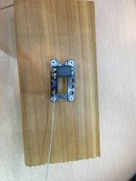
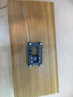
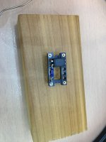
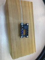
There are two ways to make this work. The simpler (and better) circuit idea came from Lars of NewClassD and it works as follows:
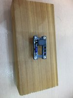
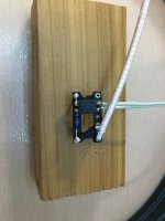
I attached a sequence of photos for the build process.
In the process I also found out that:
Have fun modding clocks!
I spent the whole day did some more clock-related works. I successfully implemented a dual Neutron Star 2 setup with proper functioning clock-enable-disable features. I hope my experiences will save some time for others doing the same mod.
1. Clock Enable/Disable Feature
Off-the-shelf clocks all support this (except specialized ones like Pulsar Clock) via Pin 1 (ENABLE) and Pin 2 (GND). The fifopi will supply Pin 1 with 3.3V if it wants the clock to run and 0V otherwise.
The NS2 clock has a similar feature, known as "Host" via a Host pad on the board. If the Host pad sees a 3.3V then the NS2 clock will be enabled, and 0V it will be disabled. To use this feature one needs to activate it by removing the solder from the bridge pads known as "Ignore" - which by default are connected such that the NS2 clock ignores the Host pad and run all the time.
There are two ways to make this work. The simpler (and better) circuit idea came from Lars of NewClassD and it works as follows:
- The Host pad is *not* used.
- The "Ignore" bridges are used as switch to turn on/off the NS2 clock.
- There are two components: an optocouple (e.g., Sharp PC817) and a 1K ohm resistor.
- All components can be installed into an oscillator socket.
- The optocoupler has 4 pins, 2 on each side.
- One side is the input, with Pin 1 connecting to the socket's ENABLE Pin (i.e., also Pin 1); and Pin 2 connecting to the socket's GND Pin (i.e., Pin 2).
- The output side: Pin 3 connects to RIGHT side IGNORE pad and the Pin 4 connects to the LEFT side IGNORE pad on the NS2 board.
- The NS2 clock output connects to the socket's Output (Pin 3) and GND pin (Pin 2).
- Make sure to solder the 3.3V bridge pads on the NS2 as it defaults to 5V output.
I attached a sequence of photos for the build process.
In the process I also found out that:
- There is no mute function in the clock module in fifopi. I attached a scope to one socket's output pins and I can see the clock signals from the other clock if it is running. That means the ENABLE/DISABLE function described above is essential if one wants to use NS2 in dual clocks setup.
- I evaluated the sound using one NS2 clock (45Mhz) and one NDK SDA (49Mhz) in a dual clock setup. My goal is to find out if having a second NDK clock (not running) in place will degrade the sound when using the NS2 clock. My results clearly showed that it does degrade the sound.
- The big question then is whether two NS2 clocks will have the same problem? My initial evaluation is that it does not suffer from the same problem as in the NDK case. Perhaps this is due to the complete isolation of the two clocks. I have not done any extensive listening yet but the initial results are very positive.
Have fun modding clocks!
Attachments
A couple addendum to the clock mod:
1. Why optocoupler?
Because the alternative is to tie the Host of the NS2 to the ENABLE pin on the fifopi, AND tie their GNDs. This degrades the sound significantly (no better than Crystek IMO) so the optocoupler is introduced to decouple the two systems galvanically.
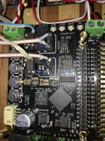
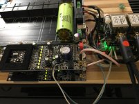
2. Dual NS2 Boards
The two NS2 clocks are powered by separate battery rails (13.2V). Although I stack them their GNDs are isolated as Nylon studs are used to mount the upper deck.
3. What's next?
If anyone is doing the same mod I recommend to also try connect the optocoupler's input pin 2 to another GND location, e.g., input power GND on the fifopi. The thinking is that there will be (tiny) current flowing from the optocoupler's pin 1 to pin 2 (to drive its internal LED) where pin 2 is also the clock signal GND. Separating the two may provide even further benefits.
1. Why optocoupler?
Because the alternative is to tie the Host of the NS2 to the ENABLE pin on the fifopi, AND tie their GNDs. This degrades the sound significantly (no better than Crystek IMO) so the optocoupler is introduced to decouple the two systems galvanically.
2. Dual NS2 Boards
The two NS2 clocks are powered by separate battery rails (13.2V). Although I stack them their GNDs are isolated as Nylon studs are used to mount the upper deck.
3. What's next?
If anyone is doing the same mod I recommend to also try connect the optocoupler's input pin 2 to another GND location, e.g., input power GND on the fifopi. The thinking is that there will be (tiny) current flowing from the optocoupler's pin 1 to pin 2 (to drive its internal LED) where pin 2 is also the clock signal GND. Separating the two may provide even further benefits.
@redjr,
Here's a great deal on 60uF polyprops (while they last):
ASC 60uF 500Vdc LTI 4-5 Series Capacitor
Greg in Mississippi
Here's a great deal on 60uF polyprops (while they last):
ASC 60uF 500Vdc LTI 4-5 Series Capacitor
Greg in Mississippi
Here's a great deal on 60uF polyprops (while they last):
Great price! Look like rolled construction rather than stacked. Probably much higher ESL, ESR, and DF vs f. Even with Wima mks4 stacked 33uf film caps, they did not subjectively audibly perform as well as smaller caps unless included in a parallel mix with some 10uf and 22uf caps. Based on limited data sheet info for the Wima parts, looks like maybe only 10uf mks4 caps are good up to 100kHz or so as we might like to have for audio amps. However, some big 60uf caps that can help at lower frequencies are probably worth trying too.
@Markw4,
I agree with your comments on the higher-frequency performance of the smaller value caps. BUT I wonder if the mks4 series are really stacked or if they are rolled, even though the cross-section shown on the product page and in the datasheet suggests they are stacked.
I say that as a friend is into using Wima MKP2 caps. He says after he Dremel's off the ends and re-terminates them with non-magnetic leads, they are a much better sounding cap that competes with many much more expensive boutique caps.
At one point he carefully took off all of plastic and potting and posted some pictures. While I can't share it here, they clearly show that series is rolled, though the diagram showing the interior construction is the same as the MKS4.
I know caps such as the Panasonic and Rubycon PPS-film SMD caps are definitely stacked, as you can see that in some of the caps. BUT I'm curious what we'd see if we took apart one of those MKS4's. Still, I'm not questioning your advice on using several of the smaller Cs, that makes perfect sense.
Greg in Mississippi
P.S. In a similar vein, in another thread we discussed what series ADM regulator chip was used in the Twisted Pear AVCC SR boards. While I linked to some comments by TP where they suggested they used the ADM7155, I pulled out the one I have here and just like the one you have, it has 2 ADM7150-04 chips. Hmmm... of course their post was over a year before I purchased my AVCC SR from them, plenty of time for them to decide their users were burning too many with the 5.5maxV ADM7154/7155 chips and move to the higher maxV ADM7150/7151 chips.
... I wonder if the mks4 series are really stacked or if they are rolled...
Don't know. However, rolled construction can perform much like stacked if extended foil construction is used, and leads are attached to the side edge of each turn of the roll in one or two places.
OTOH, the caps being sold at discount look more like the leads are only attached at the lengthwise ends of the foil, one lead at the innermost turn, and the other lead at the outermost turn.
BTW, agree with you about output stage filtering being insufficient for best sound quality (a common situation, since ESS filter recommendations are followed for many output stage designs). I used a multi-feedback 60kHz Gaussian filter for the output stage of my second modded dac, as I found SQ better that way.
Last edited:
Just out of curiosity I cobbled together a linear supply for the LiFePO4 board. I was running it with an old Acer laptop switching supply. I was pretty surprised by the positive gain in smoothness and a slightly darker background. I realise that this might be more to do with the switcher's influence on the local mains conditions and its effect on my power amp rather than the isolated Pi stack, but in any case the switcher is not getting connected again...
As Greg's signature says...Everything matters.
As Greg's signature says...Everything matters.
Just out of curiosity I cobbled together a linear supply for the LiFePO4 board. I was running it with an old Acer laptop switching supply. I was pretty surprised by the positive gain in smoothness and a slightly darker background. I realise that this might be more to do with the switcher's influence on the local mains conditions and its effect on my power amp rather than the isolated Pi stack, but in any case the switcher is not getting connected again...
As Greg's signature says...Everything matters.
Did you try it with the SMPS disconnected? If so how did that sound in comparison?
- Home
- Source & Line
- PC Based
- IanCanada's Latest RPi GB Goodies Impressions... and your tweaks, mods and hints...